Click here to read the October 2022 issue of The Flimsy Board from the Bremerton Northern Model Railroad club.
You are browsing archives for
Category: Articles
How to’s, presentations, and informational articles
Bremerton Northern September 2022 Flimsy
Click here to read the September 2022 issue of The Flimsy Board from the Bremerton Northern Model Railroad club.
David Yadock’s Dry Gulch & Western Update 11
Article & Photos By David Yadock
Dry Gulch & Western, Update 11
It has been a while since my last update. In this latest edition I’ll show you some of the new scenery that has been added to the Dry Gulch & Western layout. The alcove portion of the layout was targeted for scenery completion for the National Narrow-Gauge Convention. The convention will be held in Tacoma on September 1-4 of this year. My layout is one of many fine local layouts in the area that will be open for tours. If you haven’t already signed up for the convention, I really do recommend it. There will be lots of things to see and do. Here is the link for the convention www.seattlenngc.com , check it out today and sign up!
I decided to work on this portion of the layout to allow visitors a more complete view of my layout’s mountainous region and attempt to complete the town of Hayes River. The completed scenery in the alcove also tied together two large sections of the layout that already had scenery in place for a while. Naturally this is a progress report, some structures still need to be built, but most of the major scenery items are in place. I will continue to build structures up until the convention. Hopefully I’ll have all of them in place by September. Please don’t hold your breath on that one but I will give it my best shot!
To be a little different than previous updates I’ll show a photo progression of the scenery in this area. This will give you an idea of all the changes that have occurred over the years and how the scenery has evolved.
Photo 59 is a really old view of the layout looking down the aisle leading to the alcove. This photo shows the framework and track position. The photo also shows that the major bridges are being placed in position. Please note the large mirror in the room corner. Just a sprinkle of scenery and it is all done!
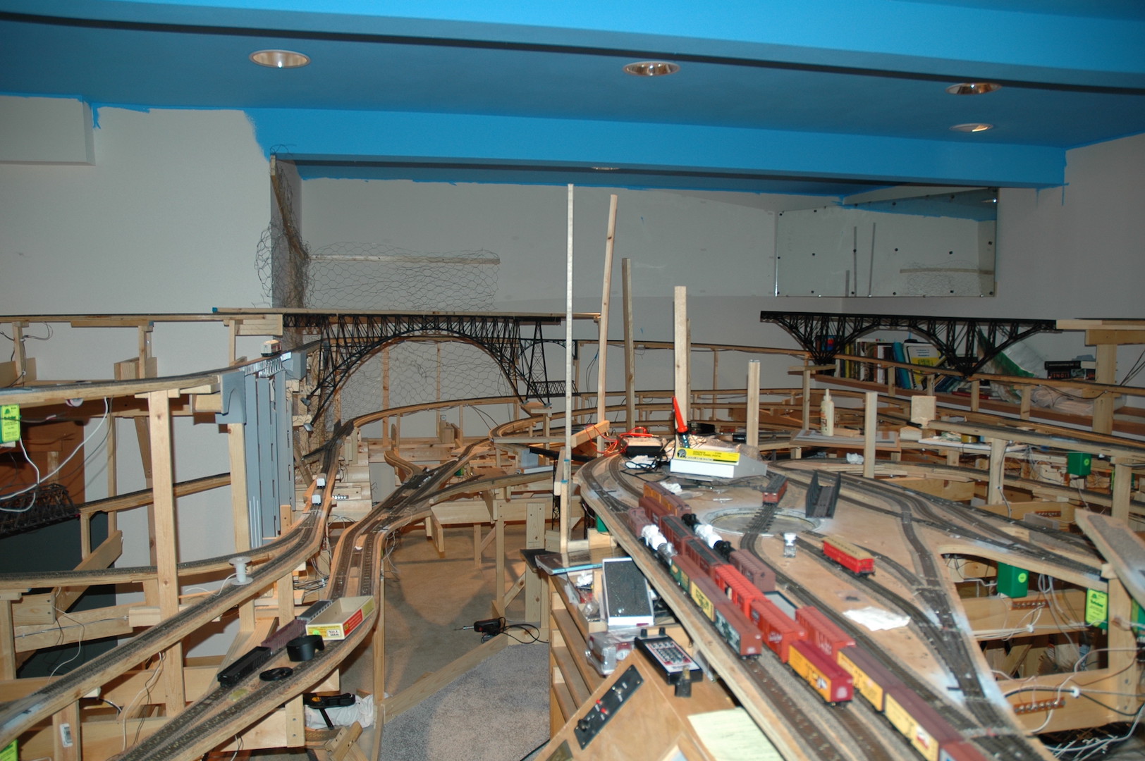
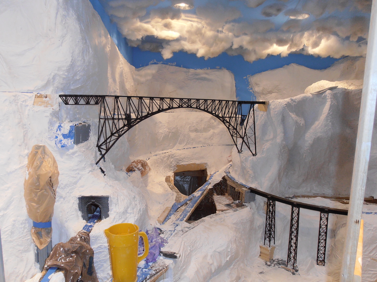
Photo 60 shows the same general area with the plaster applied. Application of Hydrocal plaster-soaked paper towels was messy but rewarding. It gave the general shape of the mountains and topography. It also reflected the overhead lighting quite well!
Photos 61 and 62 now shows some of the area with varying shades of paint applied to the plaster. This helped with the general appearance of the layout. This whole area was left dormant for quite a long time while I was concentrating my time applying scenery to other areas of the layout. The good thing about holding off with scenery application in this area allowed me to plan the types of terrain that will form the final scenery. Since I delayed scenery application I was able to re-adjust a critical access hatch. The hatch was condensed in size and shape. The retaining mechanism for the hatch was also changed to a simpler system. By changing the hatch, I gained some space to allow for another siding to be added. This increased operational capabilities in the small town of Hayes River.
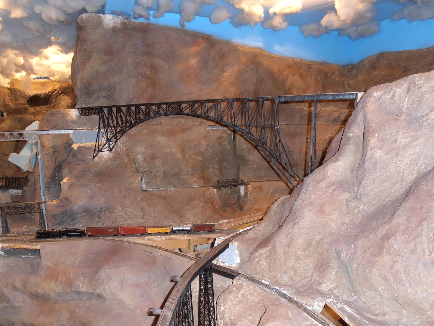
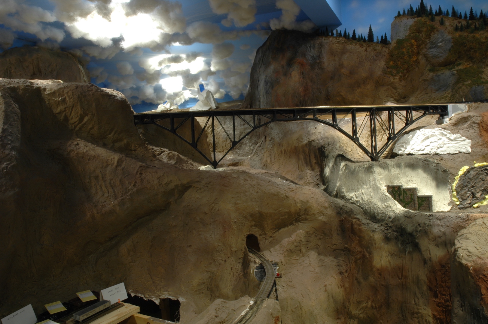
Photo 63 shows the latest version of scenery in this area. The track has been ballasted, ground cover has been applied, and various trees have been planted. Yes, structures still need to be built and installed. In the photo you can see that the town of Hayes River now has a station! It is the green structure partially hidden behind the rock outcropping.
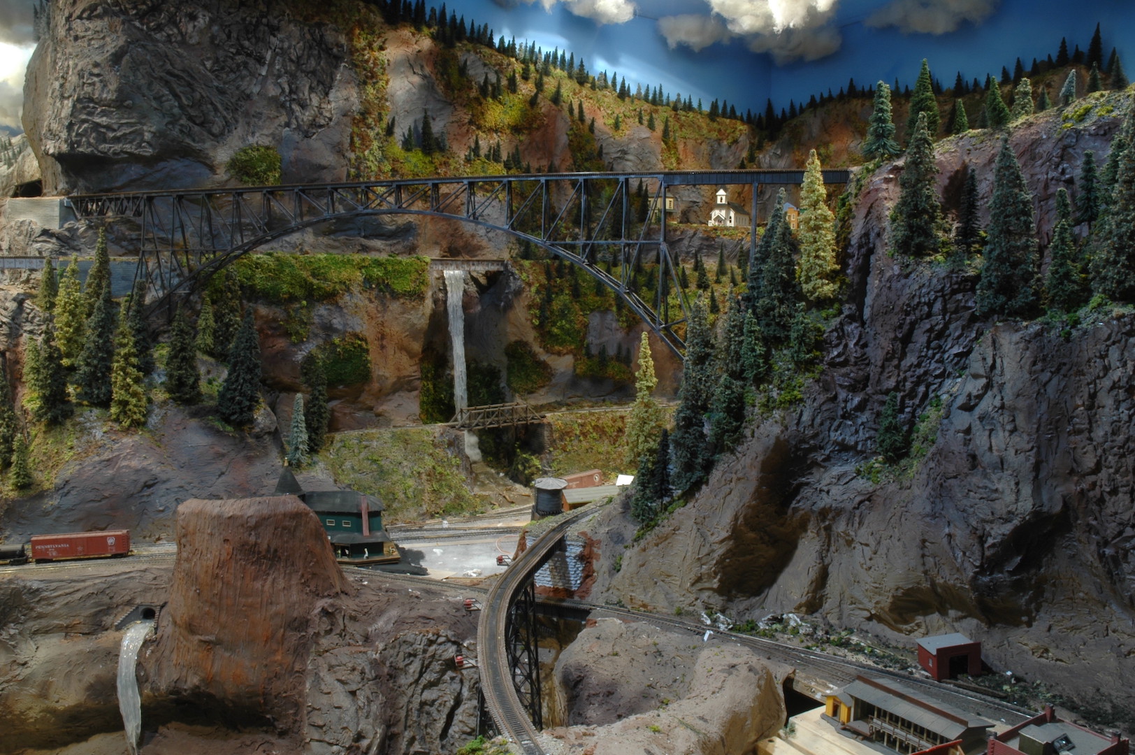
Photo 64 Is a great view of my version of the Canyon Diablo bridge. This bridge carries the mainline to the town of Alpine and beyond. As many of you know my layout is loosely based on the famous Gorre & Daphetid layout that John Allen built. On John’s layout the bridge was never completed. Due to the lack of a bridge, he never had a fully operational mainline. Early on I decided to construct all the bridges so that the mainline would be complete.
Photo 65 This is the view of a completely new hamlet on the layout. It is called Silver Hill and boasts a small flag stop station and mining operation. After the convention more structures will be added to this portion of the layout to add visual interest.
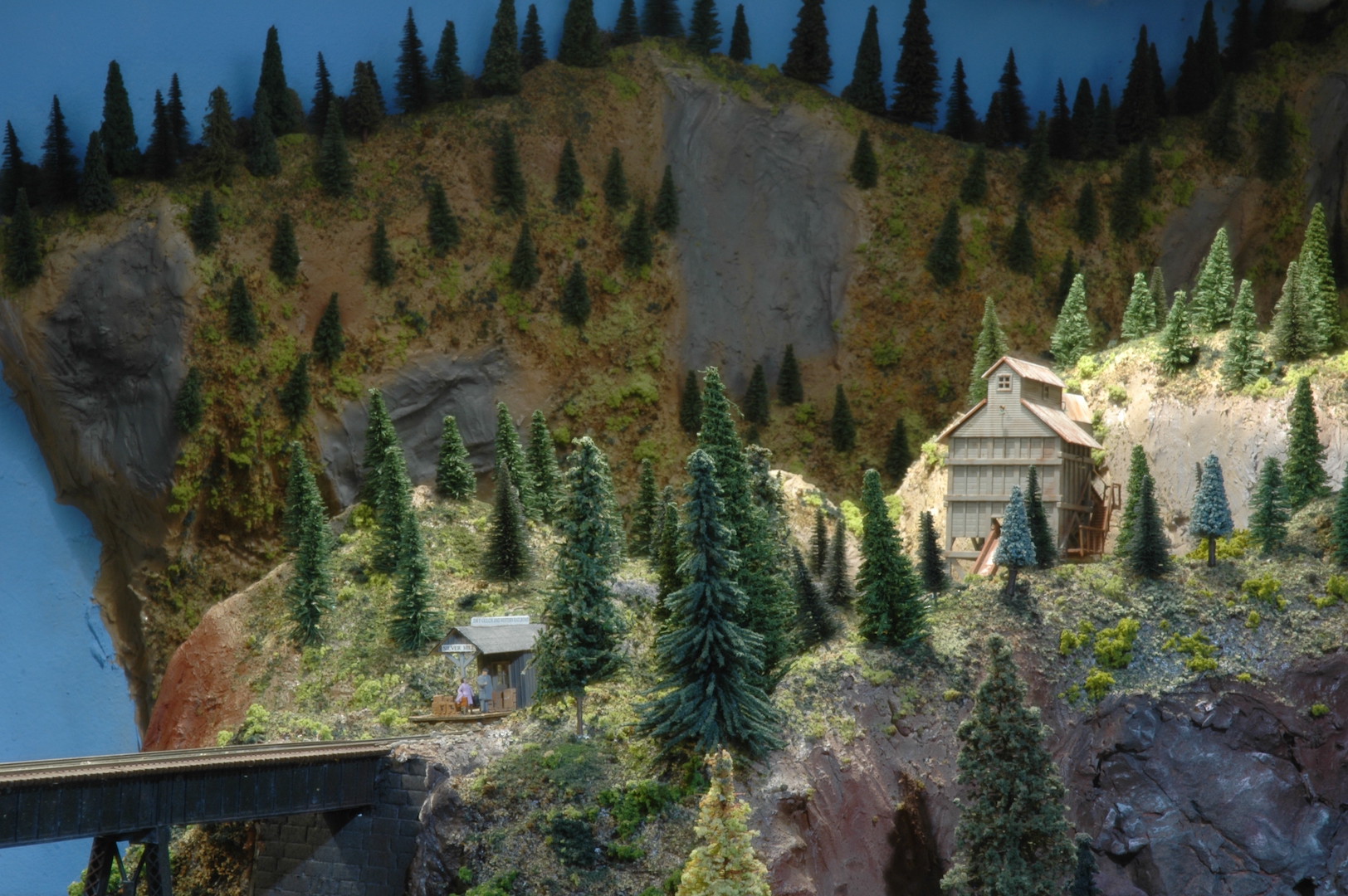
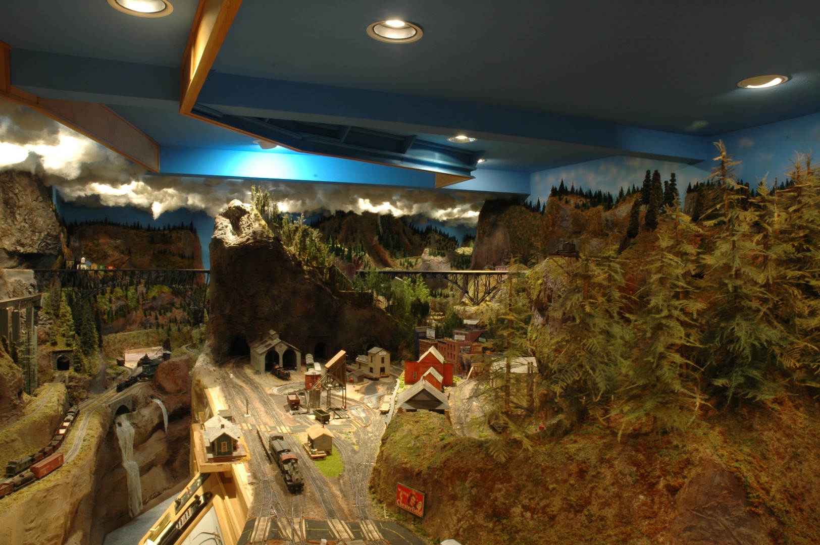
Photo 66 is a partial view of the Dry Gulch & Western layout. This is what the attendees of the National Narrow Gauge convention will be able to see during their visit to my layout. My layout is only one of the 36 excellent layouts open for tours during the convention. Everyone in the 4D should take advantage of this convention since it is right in your own backyard.
After the convention I plan on continuing scenery application to other areas of the layout. My two largest cities are still without structures! This will be my next targeted area to complete. I also have a large engine service facility to construct. So, the future holds many projects that will require my attention. I hope to see all of you 4D folks at the convention and especially when you visit my layout.
David
Bremerton Northern May 2022 Flimsy
Click here to read the May 2022 issue of The Flimsy Board from the Bremerton Northern Model Railroad club.
Puget Sound Garden Railroading March 2022 Newsletter
Click here to read the March 2022 issue of The PSGRS Newsletter from the Puget Sound Garden Railroading Society.
Bremerton Northern March 2022 Flimsy
Click here to read the March 2022 issue of The Flimsy Board from the Bremerton Northern Model Railroad club.
David Yadock’s Dry Gulch & Western Update 10
Article & Photos By David Yadock
Dry Gulch & Western, Update 10
It has been a while since my last update. I thought I would do a little different update this time. Instead of reporting on scenery progress I would report on other items taking place on the Dry Gulch & Western. There have been several additions to my locomotive fleet. All of these have been either re-builds of Ebay specials or in one instance a modification of an old AHM model. I believe more folks should take this approach for adding to their own fleet of locomotives. All it takes is some time, patience, and a few choice tools.
I have been very busy updating and weathering my freight cars. The corresponding car cards have had photos of their respective car added to them. This has been a monumental task since I have well over 200 freight cars on the layout at any given time. Now all my freight cars on the layout have some form of weathering applied to them. Operators on the layout can easily find a specific freight car since they have a reference photo of the car on the front of the car card. I admit I stole this idea from Jim Younkins!
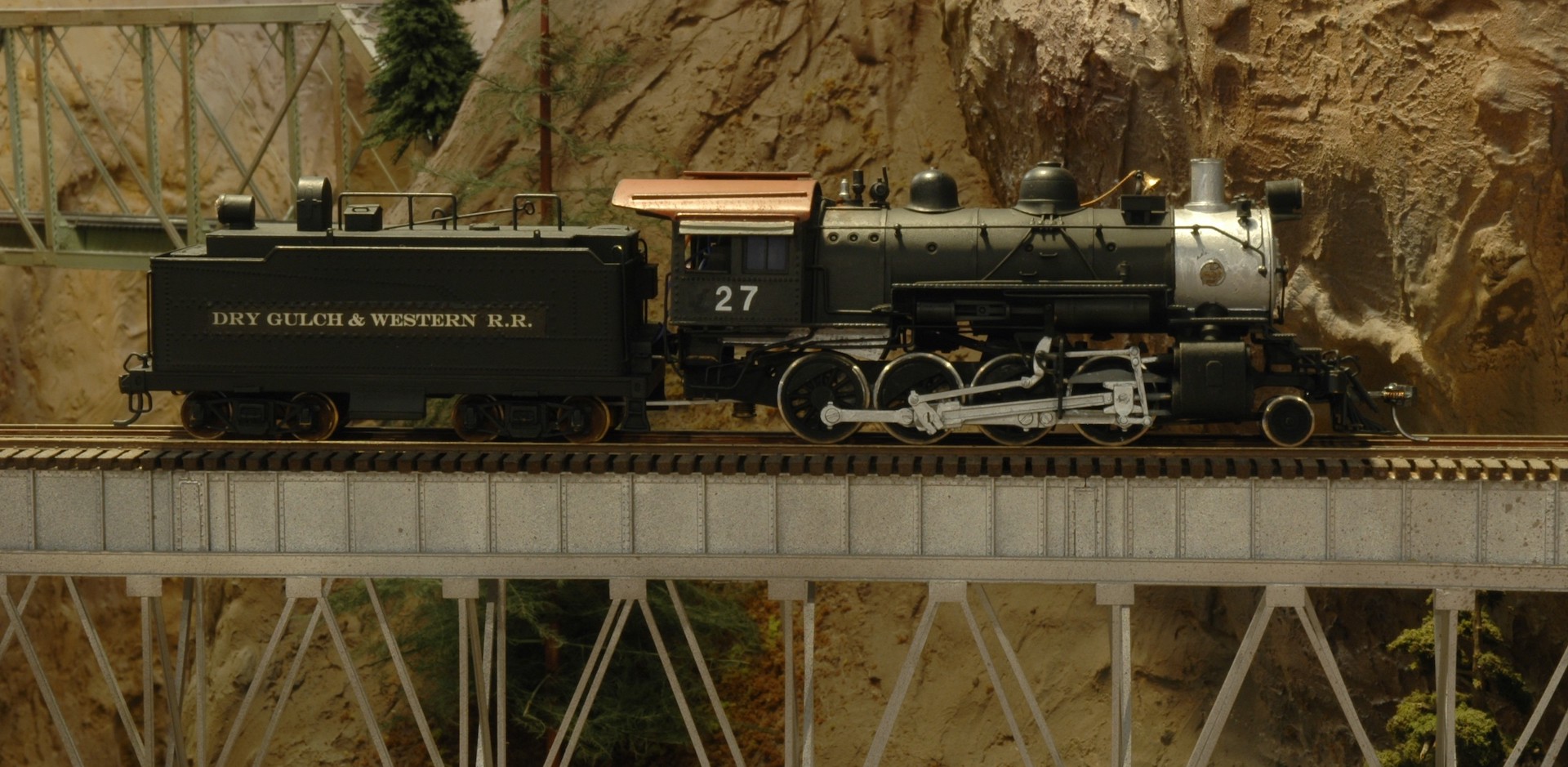
In this photo you can see the end product that was produced from another of my basket case purchases off of Ebay. This is a model of a PFM UP 2-8-0 locomotive. I’m not quite sure what the previous owner did to this locomotive, but the drivers were not in quarter. The tender was missing a wheelset and the back convex portion of the Vanderbilt tender tank was missing. I admit I have dealt with worse off locomotives but this one was in sad shape. I replaced the gearbox and motor. I installed a new motor mount, motor, and driveline. The drivers were checked for gauge and re-quartered. The cool thing about this re-build was that I could install a DigiTrax sound decoder and Stay Alive system in the tender since the back was missing. I did install new wheelsets on both tender trucks. I only needed to enlarge the holes on the tender trucks to accept the new wheelset axles. For the rear convex section of the tender, I found an old plastic Roco tank car that gladly accepted the challenge to be the donor. I was able to saw off the convex portion of the Roco tank. It almost fit perfectly into the tank of the tender. I did need to remove about 1/16” of the bottom for it to slide into the tender tank. I added a couple of stops onto the inside of the tank to keep the new convex section positioned correctly. I lightly glued it in place with Walthers Goo once the decoder was installed. The new tender back is easily removeable by gently prying it away from the tender tank wall if the decoder needs repair. Yes, it isn’t all constructed from brass, but the new paint job hides this deception very well.
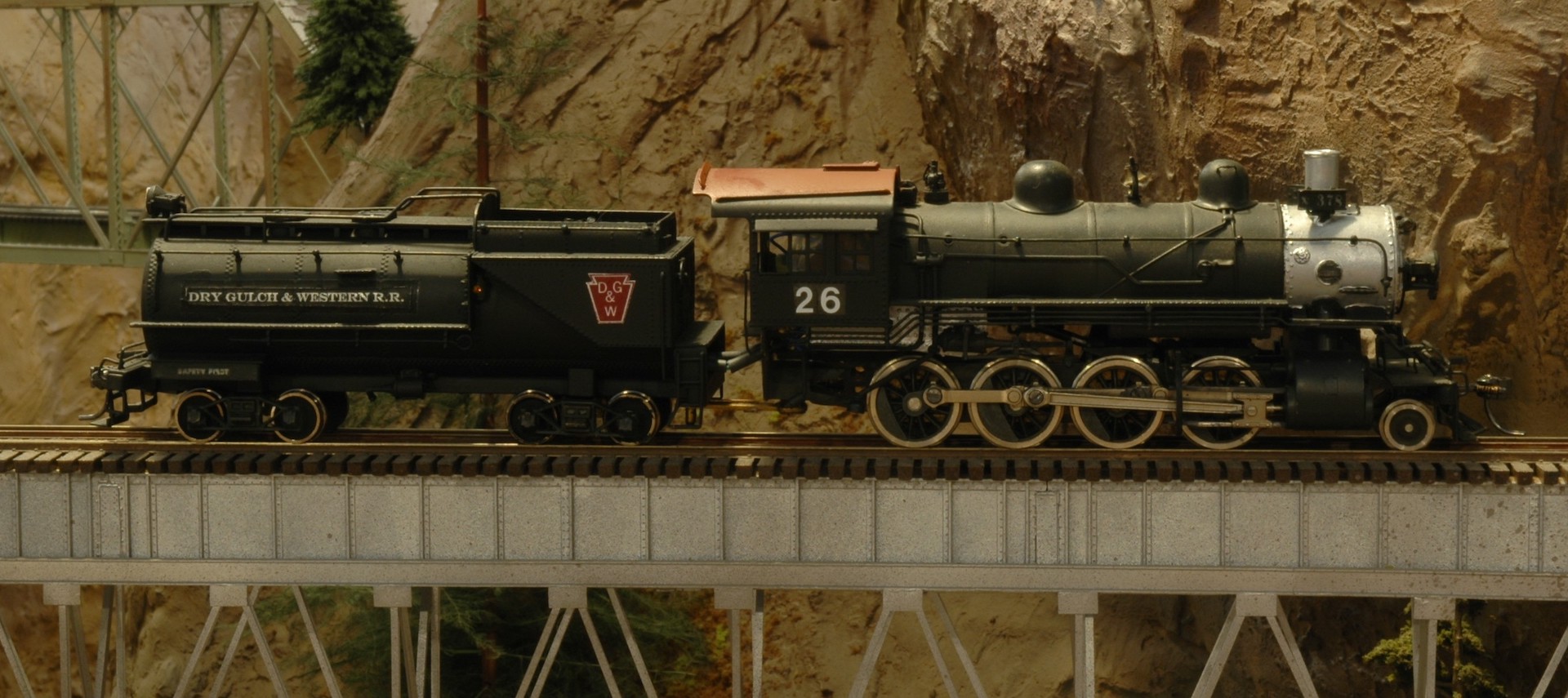
This locomotive began its life as a model of a SP C-8 2-8-0. The manufacturer is unknown. I bought it many years ago on Ebay without a tender. The locomotive had some issues since the motor was an open frame type and the gearbox/driveline was completely shot. This time the drivers were in quarter! I had an extra PFM ATSF 2-8-0 tender that was a separate Ebay purchase, so I mated the two together and produced this model. The model had a Mabuchi can motor installed with a custom mount. A new driveline was fabricated and a new NWSL gearbox was installed. This locomotive, like all my other locomotives, had several modifications. A DigiTrax sound decoder and Stay Alive capacitor system were installed. A firebox LED light, working front headlight, and working rear backup light were also installed. This old model was brought back to life and will be working on my layout for many years to come.
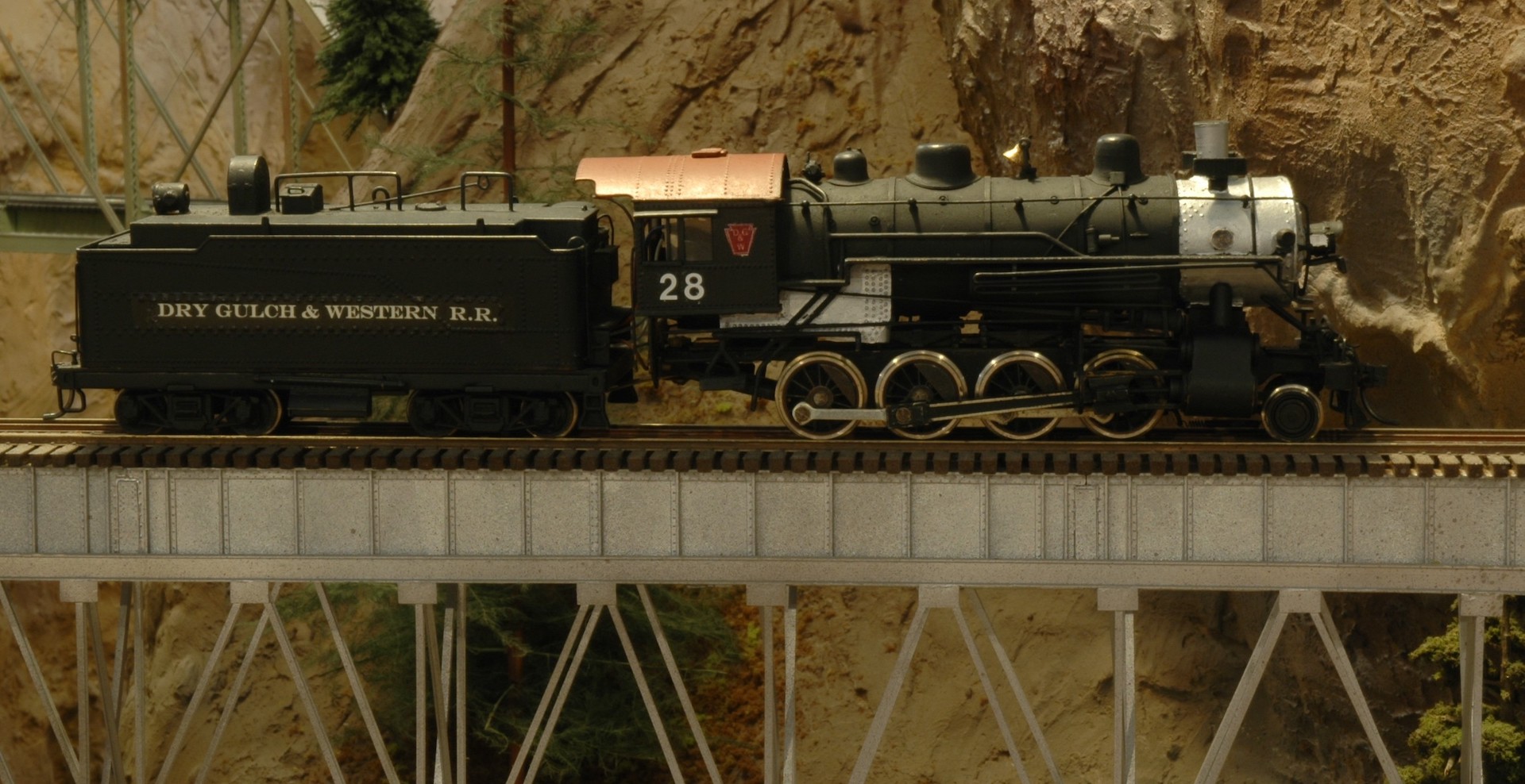
I bought this model of a PFM ATSF 2-8-0 years ago at the Boeing Employees swap meet. It was a good price and thought it would be an excellent model to run on my layout. It had already been painted, but the paint was way too gray. Even the valve gear had the same gray paint! The coloration didn’t look right. I did the normal modifications on this locomotive to make it DCC compatible. Again, a Mabuchi can motor was installed with a custom motor mount. A NWSL gearbox was installed with a new driveline. I installed a DigiTrax sound decoder and Stay Alive system in the tender. A “sugar cube” speaker was attached to the back portion of the boiler weight. It fit very well in that location and produces nice sound. A firebox light, front micro LED headlight, and micro LED back up light were installed. Of course, the locomotive was repainted and lettered for the Dry Gulch & Western.
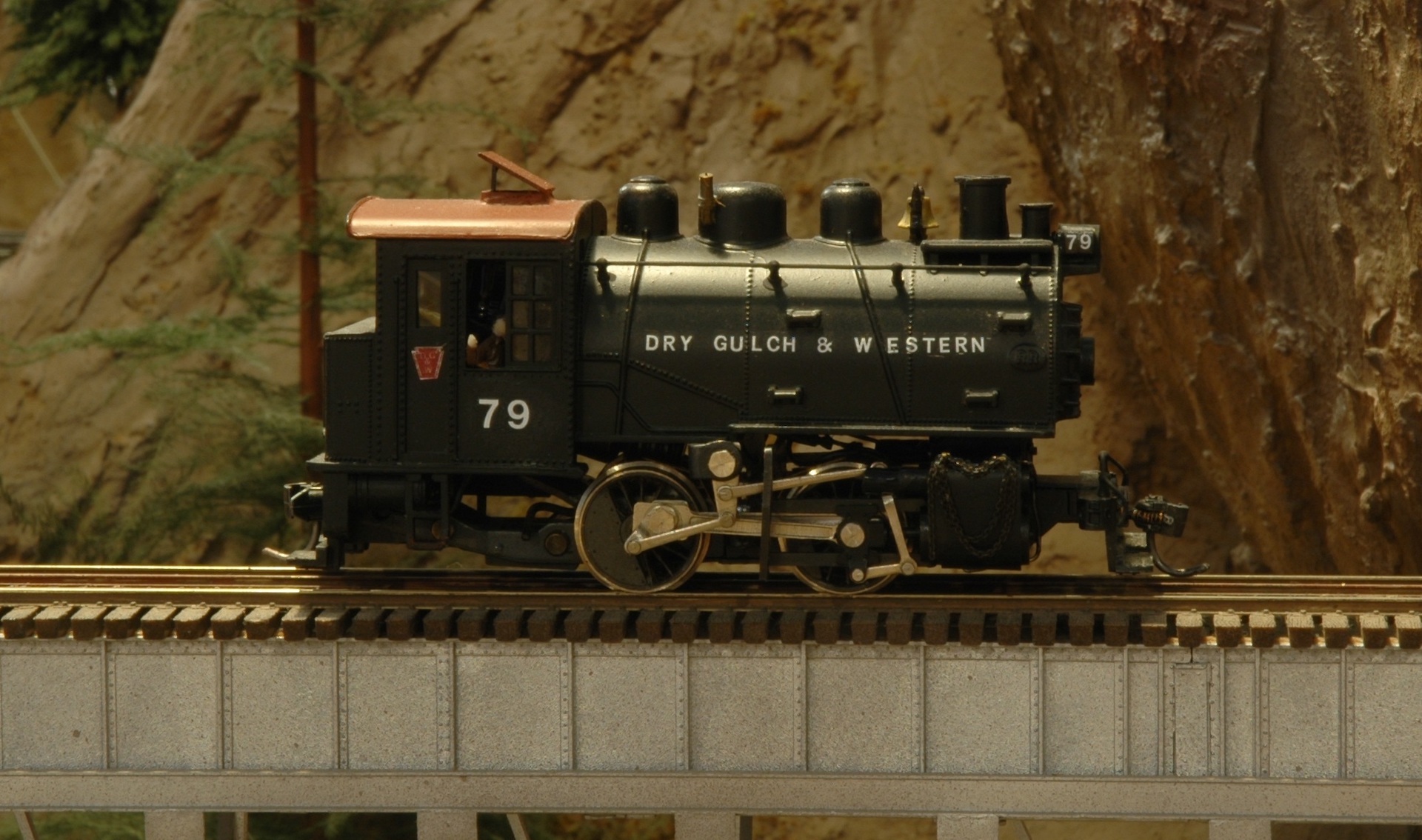
This locomotive started out as an AHM (Rivarossi) model of the famous B&O 0-4-0 Docksider locomotive. The locomotive in an unmanipulated form is a fine model if your layout has code 100 track and is not DCC! I liked this locomotive from the first time I saw it back in the 1970’s, that is why I bought it back then. I have always wanted this locomotive to be able to run on my layout. Now was the time to make some changes. My standard Mabuchi can motor was too large to fit in the locomotive without creating a custom driveline. I decided to use a smaller micro-can motor to fulfill the installation. Yes, this motor only has an 8-volt power rating, but it can be used to power this locomotive. Since this locomotive is relatively small, realistically it can’t pull a large string of freight cars, so this tiny motor will not be overtaxed. To use this motor, you only need to adjust your voltage output settings on your decoder to 6 volts. I used the original worm gear and bull gear located on the driver. I installed the old worm gear onto the new motor shaft by making a custom coupling. The original motor mount was used to mount the new motor. The wheel flanges were carefully filed down to the correct depth to allow this locomotive to run on even code 55 rail. A small Tsunami Econami sound decoder and the new Keep Alive 2 system was installed. The tiny “sugar cube” speaker was attached to the interior of the cab. Both front headlight and rear back up lights use micro-LEDs. A 5mm flicker Led was installed next to the motor to act as a firebox light. This will make for a nostalgic addition to my layout!
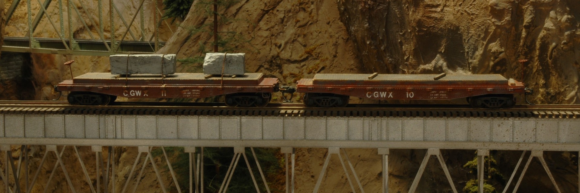
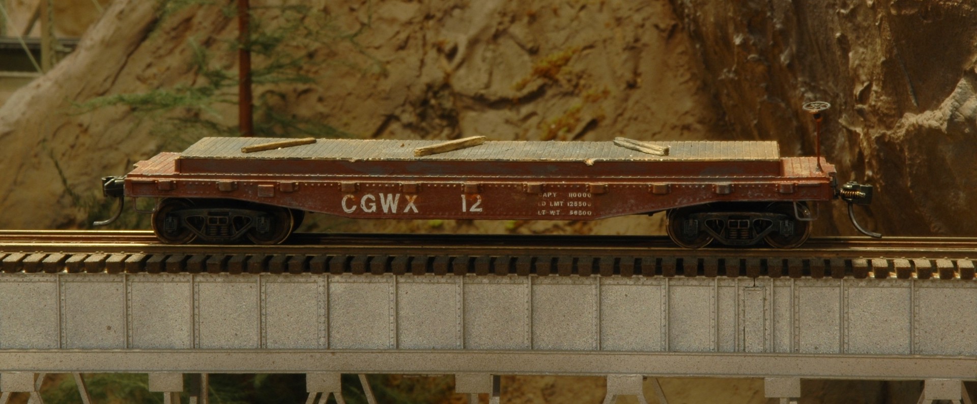
These photos are specifically for Al Lowe! They are proof of what can be done with an inexpensive old freight car. At the last Boeing Employees swap meet I bought one of these cars (Photo 59) and Mr. Lowe was intrigued by my suggested use. I already had 2 copies of this same car that were originally produced by Tyco and bought decades ago (Photo 58). They both had a strange cradle designed to carry large diameter pipe sections. I liked the short length of the car and thought they could be used as transport flats for my granite mine. I didn’t have to do much modification to them. I added some wooden decking over the odd cradle section, a brake staff, and some foot stirrups. Some weathering and a couple of chunks of “home-made” granite completed the car set. Of course, they received metal wheelsets and Kadee #5 couplers.
I thought I would present some of my “other” projects to show that you can make a silk purse out of a sow’s ear. Sometimes you encounter freight cars that really aren’t very detailed or have features that are not desirable for your intended purpose. Don’t give up on them! Just because they look odd or have strange features that doesn’t mean they can’t be modified to fit your needs. Yes, these projects do require some work, but this allows you to create a car that is more customized than the standard “off the shelf” cars. This is part of the fun. Next time I’ll get back to my scenery projects. The town of Dry Gulch is nearing completion and my expansive alcove section of the layout is having scenery applied at a record pace.
David
Bremerton Northern February 2022 Flimsy
Click here to read the February 2022 issue of The Flimsy Board from the Bremerton Northern Model Railroad club.
Bremerton Northern January 2022 Flimsy
Click here to read the January 2022 issue of The Flimsy Board from the Bremerton Northern Model Railroad club.
David Yadock’s Dry Gulch & Western Update 9
Article & Photos By David Yadock
Dry Gulch & Western, Update 9
In the last update you were able to see the new access hatch that was placed in the town of Dry Gulch. For this update, I’ll show you how it works and how this type of hatch makes life a lot easier when conducting maintenance. I would assume that there is some interest in its construction and operation.
Most modelers use a variety of ways to gain access to areas of their layout that is inaccessible from an aisle. The most common type is the simple “lift-out” hatch, this type is a simple cover to a hole in the layout. These are easy and quick to construct but difficult to actually use. One must usually find a place to put the hatch while doing maintenance.
My sliding hatch operates using a simple 1 x 4 pine board that is housed in a shaft built from four pine boards of the same size. It uses a single L-shaped lift mechanism for simplicity. Since the weight/size of the hatch is not too heavy only a single lift support is used. When raised, the hatch is held in place with a nail. A hole was drilled at a desired height completely through the shaft and hatch support. A wide pen mark on the support rails notifies the user when full extension is achieved.
Photo 47 shows the access hatch fully extended to allow access for maintenance. You will also note that the access hole is rather large to allow easy movement for maintenance. This was necessary since there are several locations on all sides of the hatch that require maintenance access.
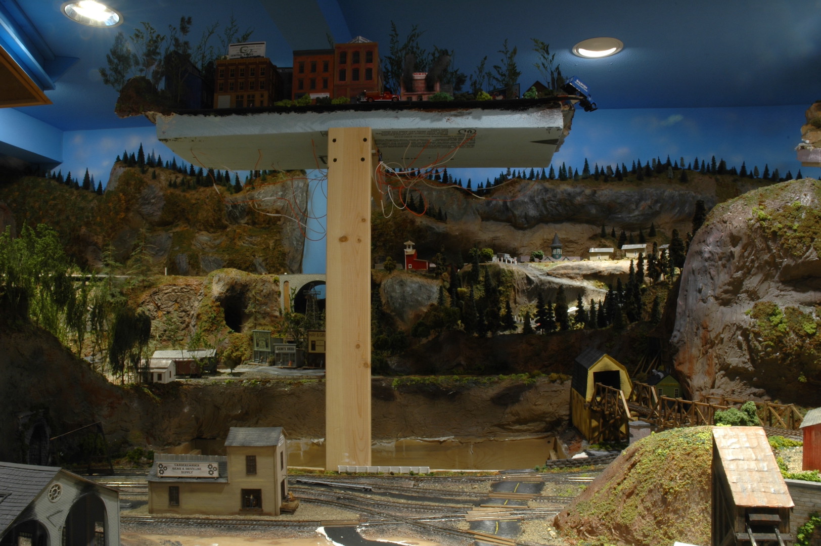
Photo 48 gives you an idea of the simple construction of the shaft. The shaft is not completely enclosed. This was done to save on wood and remove any possible binding issues of the hatch support.
Photo 49 is a close-up of the nail placement. This nail goes completely through the hatch support and shaft enclosure to ensure the hatch will not inadvertently drop down.
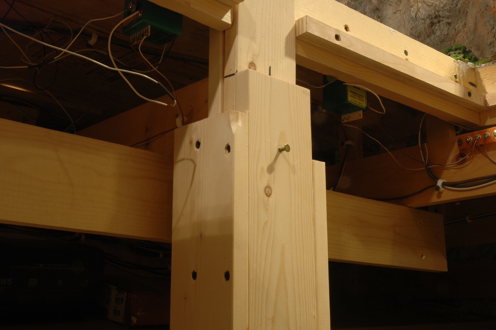
Photo 50 shows the line drawn on the hatch support. This acts as a guide when pushing the nail into the hole.
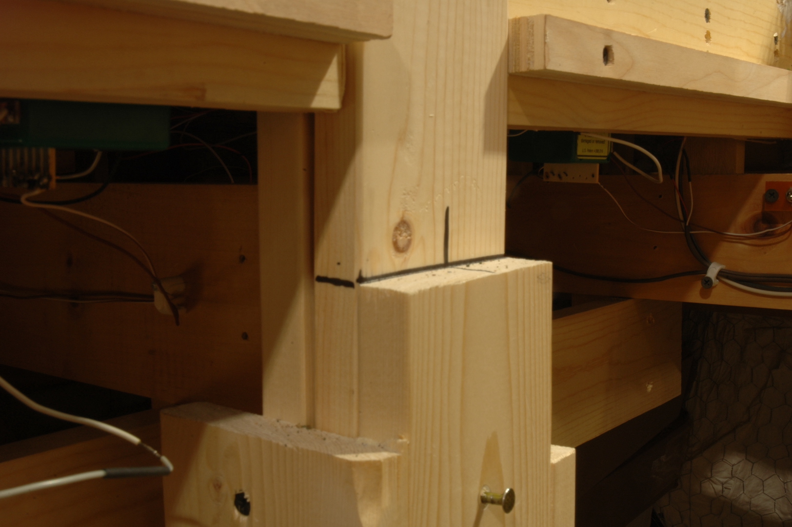
Photo 51 shows a trick I used to hide the hatch seam that runs along a roadway. I glued the back wheels of a large box van type truck to one side of the roadway that is on the hatch. The other side of the truck’s wheels are not glued down. This large truck straddles the seam and hides it quite well!
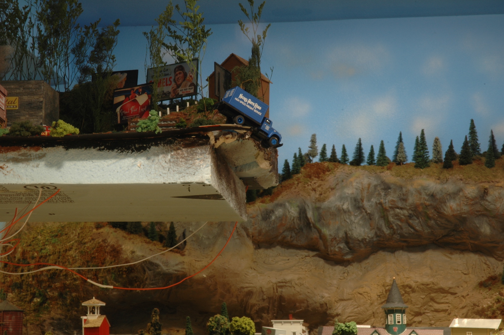
Photo 52 shows the hatch back in place. The dangling box truck from photo 47 is now back at rest on the roadway! Notice how that box van helped hide an offending seam.
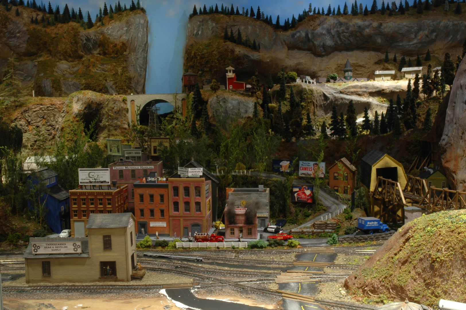
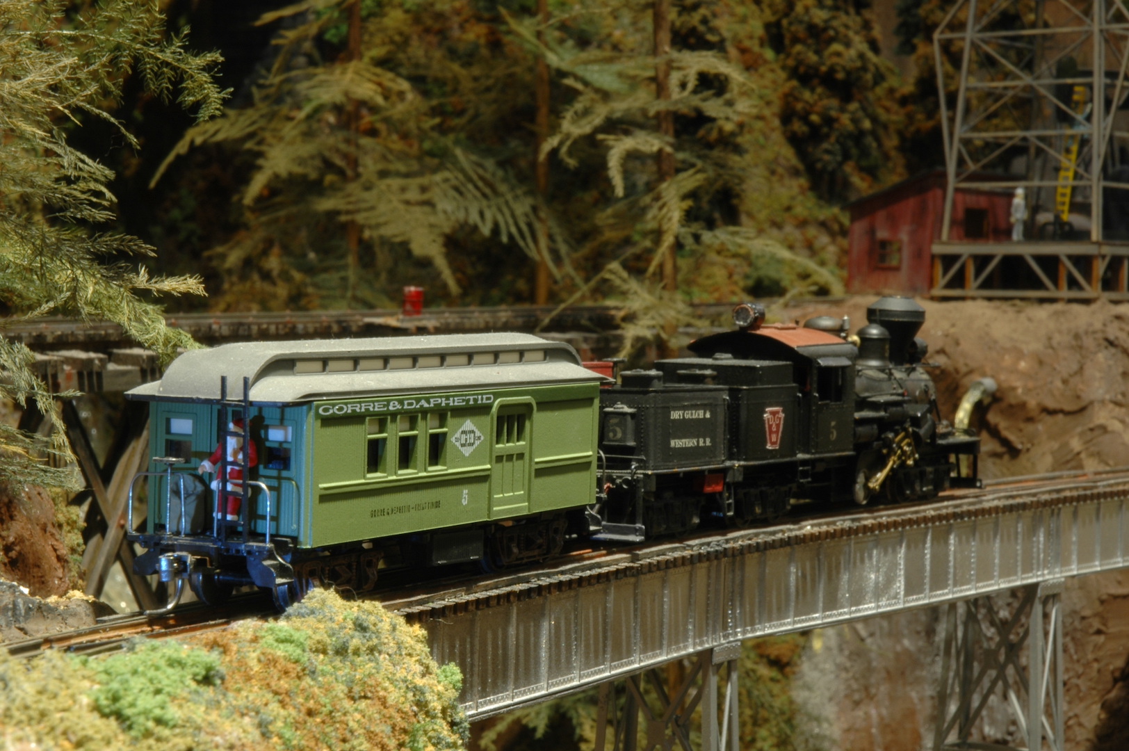
Photo 53 has Santa on his way!
In the next update I’ll show you the new scenery additions to Dry Gulch. Progress is being made on the locomotive service facilities as well as other parts of the layout. I hope everyone has a Merry Christmas and a Happy New Year.
David