Click here to read the October 2020 issue of The Flimsy Board from the Bremerton Northern Model Railroad club.
Grab Iron Posts
Remote Operating Session at the North Clinic Thursday Night, October 1
Tomorrow night you are welcome to a virtual operating session at the North End Clinic.
Keeping with our tradition of having our October meeting at Burr Stewart’s home, we are thumbing our noses at COVID and using technology at its finest to run trains over Zoom.
That being said, bring your sense of humor and patience as we navigate the Burrlington Northern from our homes. Multiple cameras have been set up all around the layout and participants will be able to run a train remotely from a web browser or a smartphone app.
The meeting will be a bit different than other Zoom sessions in the past. The clinic will start at 7pm with a quick overview of the evening. We will be utilizing the breakout room feature in Zoom for training/set up, so we’d appreciate your arriving on time. The lobby will be open by 6:50pm.
To help us prepare for tomorrow night, please complete this short survey to give us a sense of who will be attending and how you will be accessing the Zoom session.
Here is the link to the Zoom meeting for the clinic:
Topic: North Seattle NMRA Clinic
Time: Oct 1, 2020 07:00 PM Pacific Time (US and Canada)
Join Zoom Meeting
https://zoom.us/j/99299339167?pwd=Y3NndWo1VmZYYzFsRjZRd1ZqOGh6QT09
Meeting ID: 992 9933 9167
Passcode: 560771
We also put together files that will help you navigate the layout. Just click on each file name below:
Burrlington Northern Continuous Run Schematic
BNSR track plan from RMC Jan 2008 edited 200930
Burrlington Northern Continuous Loop
A special thanks to Burr Stewart, Andy Dupree, Robin Peel, Dave Enger, and Aidan Murray for a laughter-filled proof-of-concept dry run on Monday afternoon.
We are looking forward to a fun evening tomorrow night. Do not hesitate to call or email me if you have any questions.
Lisa Murray
communications@4dpnr.com
206.310.6778
The Confessions of a Hi-Railer
By Ed Ives
I’ve always had an interest in trains, cherished my trains as a child and at the age of 30-something time came to graduate to ‘Model Trains’, or so I thought. My interests lay with UK trains, the ones I grew up with and not those here. Sorry about that.
The options were to either scratch build with the use of machine tools like a lathe etc. which I do not have or kit build in O gauge or OO gauge. O gauge kits and bits were few and far between whereas OO parts were readily available and affordable, so OO kit build as a starter it was.
OO gauge is a bit of a compromise, 4 mm/ft for the structure running on HO track which is 3.5 mm/ft, so OO gauge trains are kind of narrow gauge. Perfection is needed, so I thought, true 4 mm/ft, hand built track and of course re-gauged stock. At that time in the UK there were three standards for true scale models; P4 and S4 competing standards using a track gauge of 18.83 mm and an older standard of EM gauge of 18 mm/ft. Hum, what to choose? Well 50 years ago both the P4 and S4 societies were in their formative years and maketed their own parts none of which matched what I wanted to build, LMS stock. I settled on EM gauge for the time being.
I chose to start with building some simple kits, passenger cars and choose the track standard later. I started with something really simple, or so I thought (are you getting the drift here?), a Graham Farrish kit of a LMS commuter passenger car, three of them. The kits could not have been simpler, a plastic molded body, four sides and a base as one piece, a metal channel as an frame to take the trucks and the framework between and lastly a metal curved roof, a shake the box and they are all assembled. I purchased separately sprung buffers to replace the molded ones, ventilators for the roof and lastly a book of drawings of LMS passenger cars.
A start was made on assembling the kits and using the reference drawing from the book as a guide.
- Oops, the trucks lack the foot boards that came in two different versions. No problem I can make foot boards out of thin plywood and attach to the trucks with epoxy cement. Job done.
- Oh dear the truss rod under frame was too short and made as a one piece white metal casting. Hum, do I throw them away and make new out of brass? I decided to save that for later.
- Oh, again the drawing shows all the other stuff that hangs below the floor; dynamo, battery pack, vacuum cylinders and so forth not included in the kit. I go off and make these parts as best I can.
- Door handles; grab handles and handrails were not included in the shell molding. I make these out of piano wire. The door handles were a real pain as there are so many of them about sixteen per car.
- Ah, the roof does not fit correctly with gaps at the ends of each car and resists being reformed. I get this bright idea to mold the replacement roofs out of styrene sheet. A plaster mold was made and the first production drape formed roof made. Disaster! The styrene sheet shrinks when gently heated in the oven as well as curls up something like an oversize fortune cookie. My wife is concerned that I’ll ruin the kitchen oven and calls a stop to this effort. Go back to basics and fashion roofs from thin sheet metal which become quite effective. It shows that I developed skills repairing the bodywork on my first car while at college. Rain strips made out of piano wire again, is used and soldered to the roof. Holes drilled and the ventilators added. Now we’re getting somewhere I feel.
- Oh, I wish for high frequency passenger car lighting. I build a high frequency power generator out of an old TV set and experiment with Plexiglas strips, grain of wheat bulbs and diodes to find a workable solution that fit nicely within the car. Someone suggested that I needed a license for the generator, license, what license, hum?
- The molded buffers are cut off the car bodies and the replacement sprung buffers are added. I re-gauge the wheels for EM and mount in the trucks as a test. All complete less painting and interior, I put the assembled cars on a piece of track and they look great. The nagging issue is they each weigh a ton, feel like they are made out of solid material, way too heavy for the appropriate locomotive to pull. And it only took me THREE years to do and I still have that bum under frame to deal with.
Conclusion – Life is too short to build me a scale Model Railway.
Ed Ives
The Confessions of a Hi-Railer
LAYOUT TOURS TODAY ON ZOOM
here is the link.
Time: Sep 26, 2020 10:00 AM Pacific Time (US and Canada)
Join Zoom Meeting
https://us02web.zoom.us/j/87158630632?pwd=TGtheEtTdTY5RFF4akNGbjNNV01SUT09
Meeting ID: 871 5863 0632
Passcode: 305377
One tap mobile
+12532158782,,87158630632# US (Tacoma)
+13462487799,,87158630632# US (Houston)
Russ
206 200 2211
What Do You Think
There will be a General Meeting of leaders of the Board, clinics and modular groups this Monday evening at 7PM. We will look ahead based on our experience with the new ways we have made adjustments because of COVID 19. How can we do more and how can we do things better? How can you get involved?
Please feel free to look in and share any suggestions you may have to make our sharing of the hobby better. Here is the link to the meeting:
Topic: 4D General MeetingZoom Meeting
Time: Sep 21, 2020 07:00 PM Pacific Time (US and Canada)
Join Zoom Meeting
https://us02web.zoom.us/j/85366397557?pwd=YS9YQnFzZGtpZGpqeXpHa0xsYm01QT09
Meeting ID: 853 6639 7557
Passcode: 845634
Call me if you have questions.
Russ 206 200 2211
David Yadock’s Dry Gulch & Western Railroad – Part 7
Article & Photos By David Yadock
Dry Gulch & Western, A Photo Series Part 7
I’m sure many of you have been wondering about my freight car fleet. In the early years I had just about every siding and all the yards full of cars, but I learned! Now I keep around 100 or so cars on the layout. Since I have become involved with operations I try keep the yards about 1/3 full of cars. This helps or sometimes hinders car sorting for yard operators. I do have around 250-300 cars in total with most being stored on specially constructed shelves. All my cars have had metal Walthers Proto wheelsets installed on them along with standard Kadee #5 couplers. I did test Kadee “scale” couplers on some of my cars but found they did not couple well with the standard #5 couplers in certain situations, they have since been removed from those cars. My fleet of cars come from many various manufacturers and most are older non-superdetailed cars. I still can’t believe that some of my early cars that I have on the layout were purchased for 50 cents each! On my layout you can find a mix of AHM, Roco, Atlas, Athearn, MDC, Tichy, Varney, Ertl, Life-Like Proto, Ulrich, Tangent, and Accurail models all working on the layout. I still have the three original AHM freight cars from my very first train set, yes are on the layout! Regarding freight cars, I have found the key is to have them all run and perform well. If they do not, then they get pulled from the layout, tagged to identify the problem, and replaced with another car. There are plenty of replacement cars waiting in the wings to go onto the layout. Also, if you have been noticing, there are a lot of east coast railroads represented in my freight car fleet. Originally, I was thinking of creating a layout that would be based on the prototype Pennsylvania RR. That didn’t happen. I still kept the cars for the Dry Gulch & Western and used whatever road name that I liked. I admit, if the car has eye-catching graphics that is a plus. Another issue, the cars do not fit any specific era. Yes, I have billboard reefers that ride on arch bar trucks. I even have some ancient wooden passenger cars. I do try to have freight cars that are generally from the steam era. One thing I still do not have are some home road freight cars. I have a few but there are still a lot of freight cars in boxes that need to be built and lettered specifically for my railroad. Like with all model railroads there is always something that needs to be done.
Photo 31 shows a closer view of the tunnels and the right abutment of my version of the Canyon Diablo Bridge. This view shows how I attach some rock plaster castings. I use expanding spray foam. The surrounding areas behind the casing will be filled with joint compound. The joint compound will be carved and then painted. Ground cover will be added later.
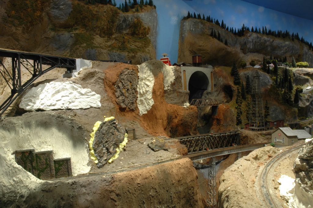
Photo 32 shows a full view of the bridge. In the bottom corner of the photo you will see a silver SP gondola, one of my original “trainset” cars! Note how the mirror in the corner allows the room to expand. The mountain to the left is completely hollow along the backside. That gives me plenty of access to the track in that area.
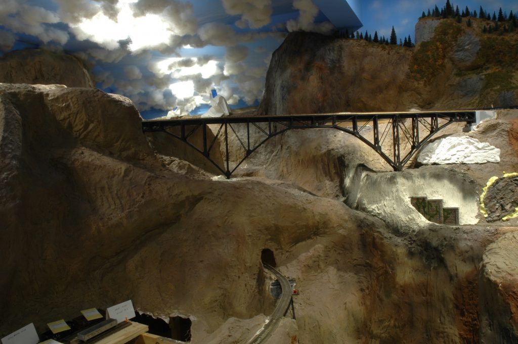
Photo 33 shows a closer view of the bridge. The bottom steel work does not support the bridge. There is a one-inch aluminum channel that runs the length of the bridge, it carries all of the weight. The channel is supported in both ends by solid wood abutments attached to the benchwork.
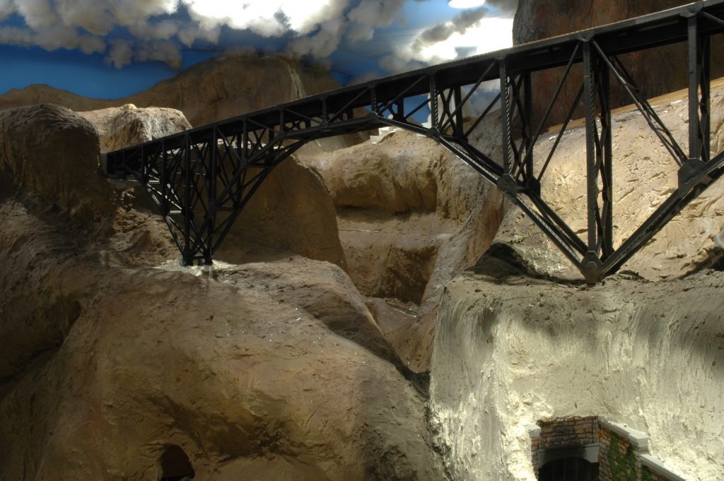
Photo 34 shows the central mountain. The mainline curves around to a second large bridge. Just like John Allen’s Gorre & Daphetid layout I have a spiral at the base of this mountain.
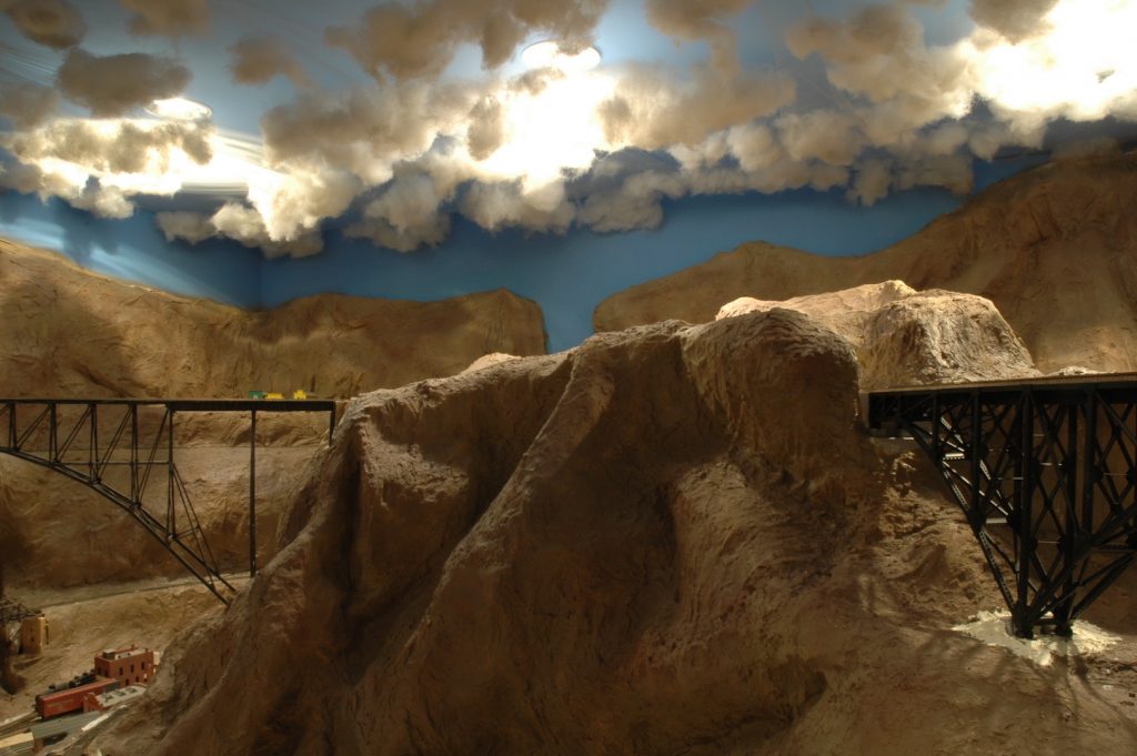
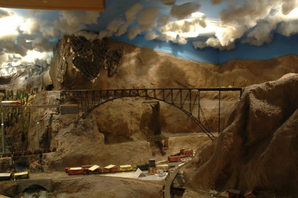
Photo 35 shows the second arch bridge. This is a close replica of the Vance Creek bridge located just out of Shelton WA. It is made from styrene with brass inserts for structural support. This bridge was constructed on a saddle shaped jig. Construction of this bridge was several months long. My model bridge towers over the town of Hayes River. To the extreme left you can see some of the snow-covered mountains and even more bridges. My freight trains are constantly gliding over bridges, blasting through tunnels or snow sheds, and battling tough grades with tight curves to move freight over the mainline through the mountains. Next time we will check out more of the bridges on the layout and give you a peek at the valley that is on the left.
That is it for this week.
David
September 2020 Eastside Virtual Get Together Clinic
By Alex Brikoff
I’m happy to announce our next Eastside Clinic will be held virtually on ZOOM on Thursday, 09/17, starting at 7:00 PM with our virtual lobby opening at 6:45 PM. We have switched back to Thursdays by popular demand! Since our clinics are virtual these days, I would like to extend an invitation to all the 4th Division to attend next Thursday. So be sure and save the date for the September Eastside Clinic next Thursday, 09/17 at 6:45 PM! The log in info for the clinic is below.
Topic: September Eastside Virtual Get Together Clinic
Time: Sep 17, 2020 06:45 PM Pacific Time (US and Canada)
Join Zoom Meeting
https://zoom.us/j/96569499645?pwd=TDc0Nk5ubVArUTEvYVZEQXo4cFBqQT09
Meeting ID: 965 6949 9645
Passcode: 613377
Our Clinic this month is titled “The Everett & Monte Cristo Ry in Trainz” and will be presented by Didrik Voss. Didrik is a very talented local modeler and a NMRA MMR. He has prototype modeled the Everett & Monte Cristo Ry, circa 1900, in his basement. However, he was only able to model 2 miles of the 68-mile route. As a result, he began modeling the remaining 66 miles on the computer using Trainz. This clinic will be a walkthrough on what has been accomplished so far. Please realize, this is 68 real miles, plus all of Everett with the GN and NP lines overlapping. If the interest is there, he would be happy to get into more detail on how to create the Everett & Monte Cristo Ry in Trainz.
After the Clinic, we will have some time for other folks to show off their latest model work in our “Show and Brag” segment. The Clinic will wrap up with some administrative comments.
Alex
Fine Scale Miniatures For Sale
By Richard Hoffmeister
FOR SALE: A number of assembled and detailed HO dioramas and buildings from Fine Scale Minatures kits. Located in Pierce County, Washington – cannot be shipped. For prices please contact richardhoffmeister@comcast.net
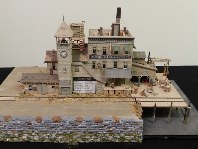
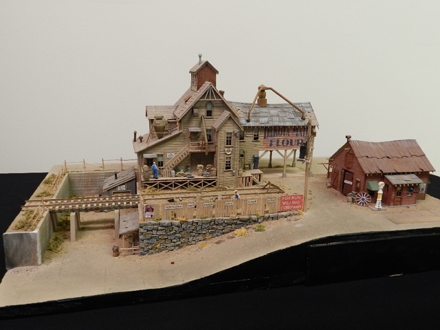
Saturday’s 4DPNR Zoom Layout Tours!
By Burr Stewart
Join the 4th Division this Saturday, Sept. 12, at 10:00am, on another pair of exciting Zoom virtual layout tours, by Brian Ferris and then Janice and Barry Dupler. Brian is from Olympia and has an HO layout to show us that features south sound scenery and structures, with an emphasis on realistic Timetable and Train Order operations made accessible even for first time operators. Janice and Barry Dupler have an HO/HOn3 layout in Bellevue that features some wonderful bridges, complex track work, towns, and soaring rock faces that only a narrow gauge line could conquer. Here are the details for joining the Zoom meeting:
Time: Sep 12, 2020 10:00 AM Pacific Time (US and Canada)
Join Zoom Meeting using this link:
https://us02web.zoom.us/j/88513613667?pwd=RDR4dGNJaU9vbkI3ckUzT09KREUzQT09
Meeting ID: 885 1361 3667
Passcode: 786815
BRIDGE-BUILDING BASS-ACKWARDS
Article and Photos by Rich Thom
Readers who have crewed on my HO-scale Coldwater Creek & Cascade RR during the past eight years have been greeted when entering the layout room by the scene in Figure 1—a granite defile spanned not by proper bridges but two pieces of ½” plywood subroadbed. When I started my layout in 2008 (having been away from the hobby since 1962) I sought the advice of local experts about the construction sequence for a layout designed for operations, which was entirely new to me. All advised laying track and beginning op sessions as soon as possible, leaving scenery and time-intensive structures such as bridges until later, so that the operation scheme and track plan were debugged first. It was good advice, but I didn’t quite follow it. Unhappy with my bare plywood empire I charged ahead and completed the scenery next, leaving the plywood spans in place where bridges would be, well, “someday.” That left the conundrum shown in Fig 1: scenery 90-percent finished—but no bridges. I had two choices here. I could cut away the temporary spans, removing the track, cork roadbed and subroadbed entirely, then build the bridges the usual way, from the ground up. However, I had seen an article in Railroad Model Craftsman (“Building Trestle at North Crags” by John Olson, Dec 1978) in which the author described cutting the subroadbed away, but keeping the rails in place, then building the bridge and abutments underneath them. More or less bass-ackwards! The advantage, especially for a bridge or trestle on a curve, is the preservation of smooth curvature as well as precise level across the span. That seemed appealing so I have built most of my bridges in this manner.
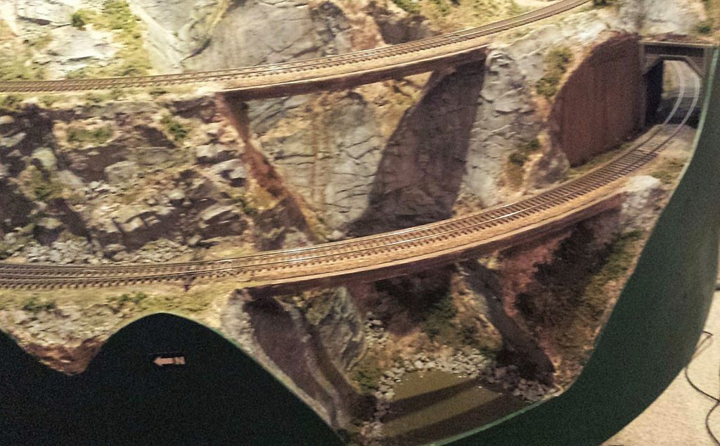
I’ll use the example of my Silver Falls Bridge, the upper span in Fig 1, to describe the construction sequence. The 1:87 pile driver crew came out to the site to have a look at the sheer granite walls on each side and, after a few unkind words about the railroad’s surveyor, announced that no piles could be driven there. Some sort of single span was needed rather than a pile trestle. My modeled year is 1928 so I could have prototypically selected a steel girder span—I have them elsewhere on the layout and it would have been far easier—but since this was a foreground model I chose a timber deck truss bridge, with its fussy tension rods and nbw’s. I used a Kalmbach publication plan, shortened by one panel to fit my 50-foot span.
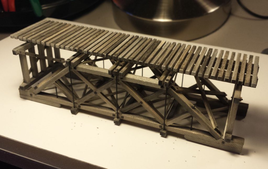
Building the deck truss bridge used standard methods at the workbench (Fig 2). Stripwood and bridge ties are from Mt. Albert Scale Lumber (now distributed by Fast Tracks), pre-stained with Micromark Bridge and Tie Stain. Having tried several glues, I use Aleene’s Tacky Glue, either standard or fast-grab variants depending on whether the workpiece is held tightly in a jig, or needs the fast-grab action. Nbw’s are from Tichy Train Group. Tension rods are 0.028” brass wire or 2.4” in HO, just slightly oversize but easier to see.
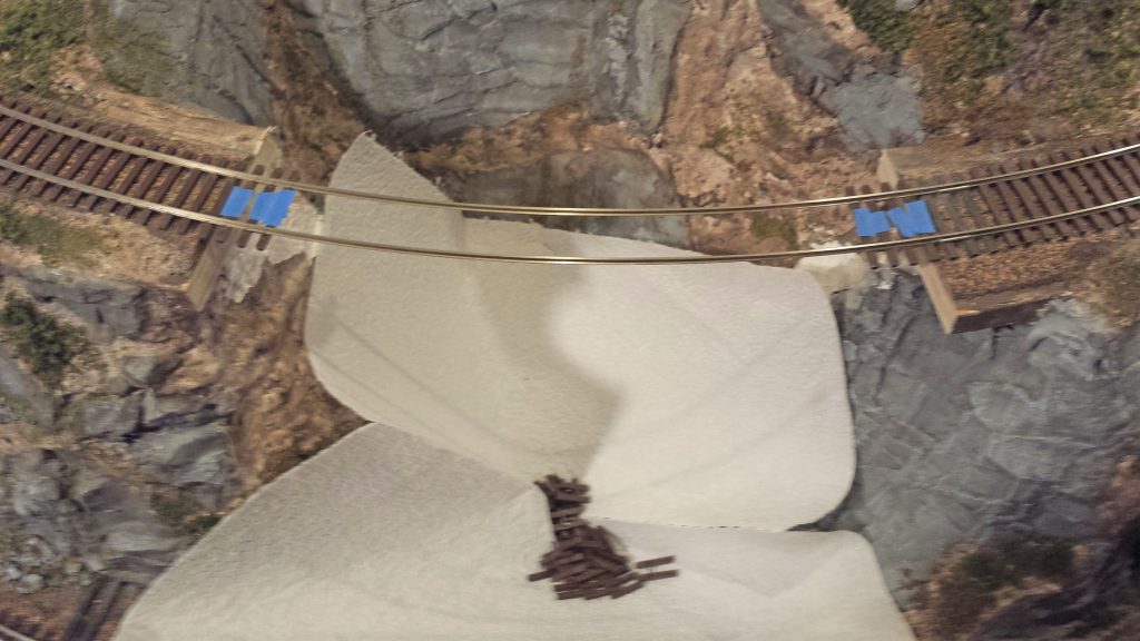
Now for the fun part! First the plywood subroadbed and cork roadbed were cut away (Fig 3) using a Zona 5” saber saw blade. The granite rock faces by the way are Cripplebush rubber rocks, which though more time-consuming to paint than plaster or resin alternatives, I am very pleased with. I presented a Skagit Valley & Whidbey NMRA clinic on their use in 2016. Next the flextrack plastic ties were removed. The blue painter’s tape marks ties that are to remain in place; these will be set in ballast on the concrete abutments.
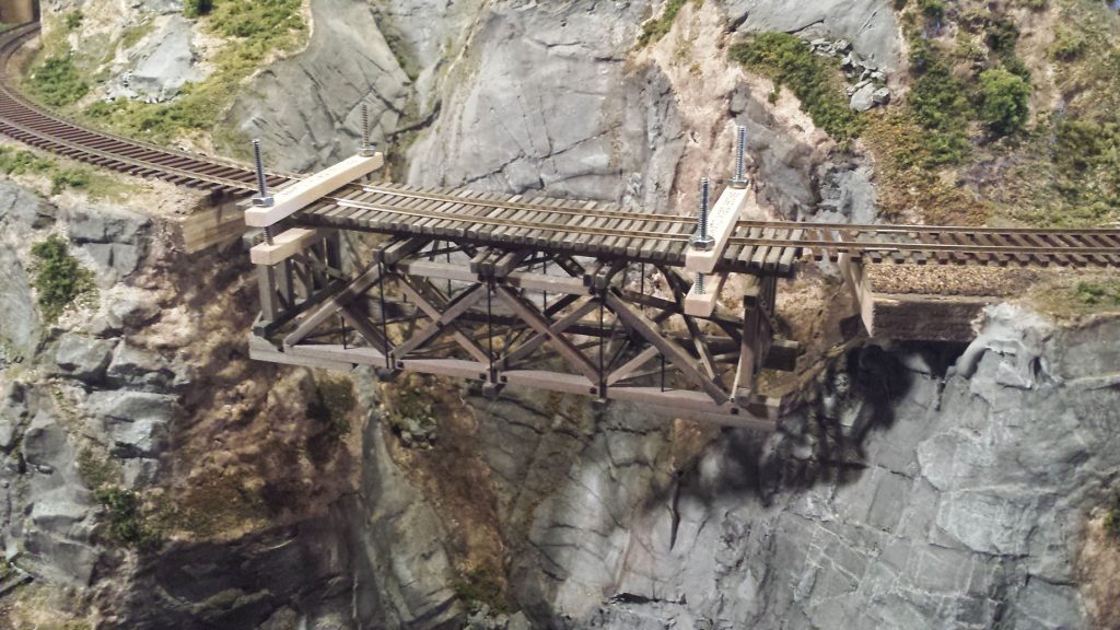
The next step, Fig 4, was to carefully clamp the pre-fabricated span to the rails. None of the clamps in my toolbox was quite right for the job, so I jury-rigged the pair seen here. Alignment is important; to get it right I drew pencil lines on the bridge ties for locating the rails.
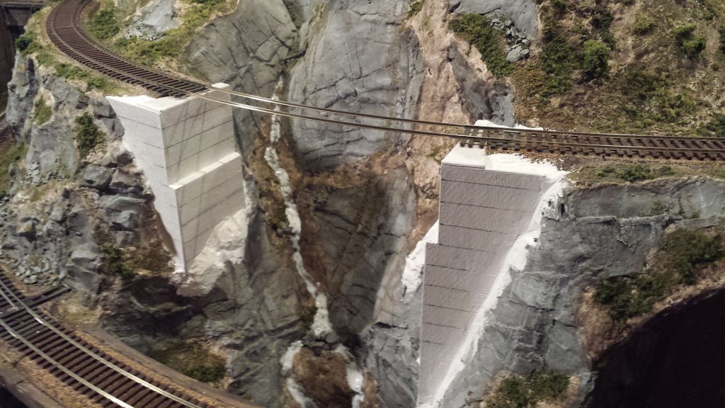
The next step was to build the abutments below the suspended bridge span. I used basswood and artist’s mat board to simulate concrete abutments, sealing the mat board well so that it didn’t warp with subsequent applications of acrylic paint. This is the most tedious step in the sequence, requiring a number of height measurements from tie level to the pre-existing terrain. In Fig 5, the abutments are completed and ready for painting. They were blended into the existing rock terrain with Sculptamold, which was then carved with striations to match the features of the rubber rocks. All was then given a coat of white acrylic gesso. I used gesso liberally in my scenery coloring as an undercoat, to even everything out over varying materials and increase reflectance and brightness, a trick I learned from my artist son. The white stream below the span is a coat of gloss mod podge which will dry clear; this was unrelated to the bridge work and just done at the same time.
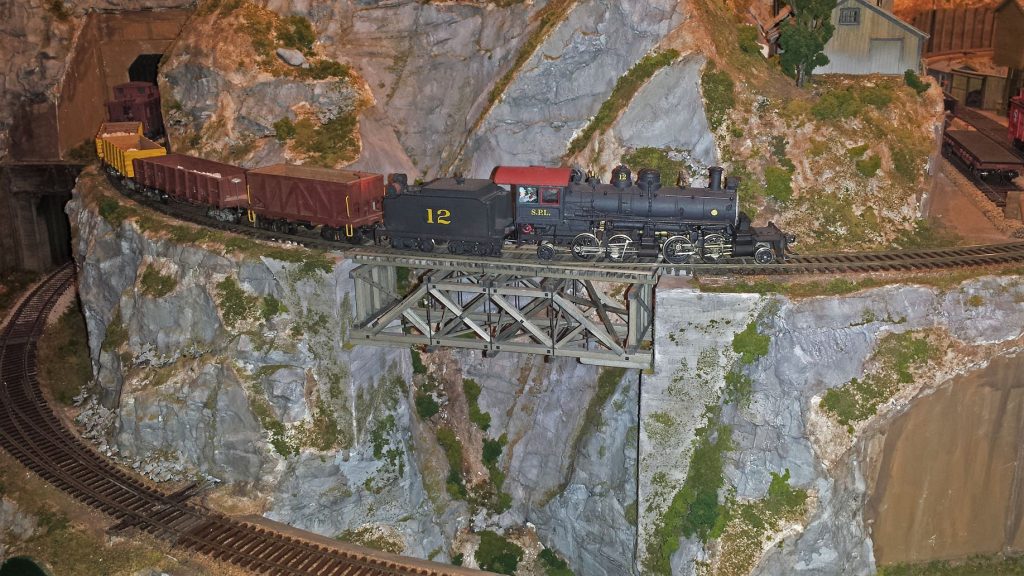
The bridge span was repositioned into place and rails spiked to the bridge ties. Guard timbers and their nbw’s were added as a final step. The completed Silver Falls Bridge is shown in Fig 6, with the CC&CRR’s heaviest loco—a 2-4-4-2—giving the bridge an axle-load test; it passed. I sized timbers and other features for an E-55 rating, or slightly lower. The abutments were weathered with India ink washes and Bragdon powders, and some simulated foliage and moss added.
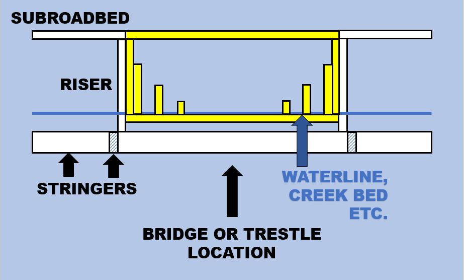
I’m not recommending that you build your bridges this way, but having boxed myself in by largely completing my scenery before tackling the bridges, it worked satisfactorily for me. There are several better ways, only one of which is illustrated in Fig 7. The idea here is, when you build your basic layout framework—stringers, risers, subroadbed—instead of keeping the subroadbed continuous across your future bridge locations as I did, construct a removable “bridge frame,” highlighted in yellow in the figure. It’s built of 1 x 3’s or 1 x 4’s or whatever your chosen lumber size is, and includes abutment and pier supports as shown. Lay your track and begin op sessions and run for years this way if you want to—but don’t complete the scenery around the bridge frame. When you’re ready to build your bridge or trestle, remove the frame, the top piece of subroadbed, and build the bridge on the frame at the bench. Reinstall the bridge frame with its completed bridge and fill in the scenery around it. Maybe on my next layout!
###
