Article and Photos by Rich Thom
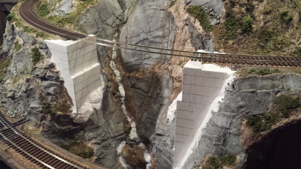
Readers who have crewed on my HO-scale Coldwater Creek & Cascade RR during the past eight years have been greeted when entering the layout room by the scene in Figure 1—a granite defile spanned not by proper bridges but two pieces of ½” plywood subroadbed. When I started my layout in 2008 (having been away from the hobby since 1962) I sought the advice of local experts about the construction sequence for a layout designed for operations, which was entirely new to me. All advised laying track and beginning op sessions as soon as possible, leaving scenery and time-intensive structures such as bridges until later, so that the operation scheme and track plan were debugged first. It was good advice, but I didn’t quite follow it. Unhappy with my bare plywood empire I charged ahead and completed the scenery next, leaving the plywood spans in place where bridges would be, well, “someday.” That left the conundrum shown in Fig 1: scenery 90-percent finished—but no bridges. I had two choices here. I could cut away the temporary spans, removing the track, cork roadbed and subroadbed entirely, then build the bridges the usual way, from the ground up. However, I had seen an article in Railroad Model Craftsman (“Building Trestle at North Crags” by John Olson, Dec 1978) in which the author described cutting the subroadbed away, but keeping the rails in place, then building the bridge and abutments underneath them. More or less bass-ackwards! The advantage, especially for a bridge or trestle on a curve, is the preservation of smooth curvature as well as precise level across the span. That seemed appealing so I have built most of my bridges in this manner.
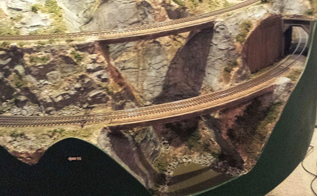
I’ll use the example of my Silver Falls Bridge, the upper span in Fig 1, to describe the construction sequence. The 1:87 pile driver crew came out to the site to have a look at the sheer granite walls on each side and, after a few unkind words about the railroad’s surveyor, announced that no piles could be driven there. Some sort of single span was needed rather than a pile trestle. My modeled year is 1928 so I could have prototypically selected a steel girder span—I have them elsewhere on the layout and it would have been far easier—but since this was a foreground model I chose a timber deck truss bridge, with its fussy tension rods and nbw’s. I used a Kalmbach publication plan, shortened by one panel to fit my 50-foot span.
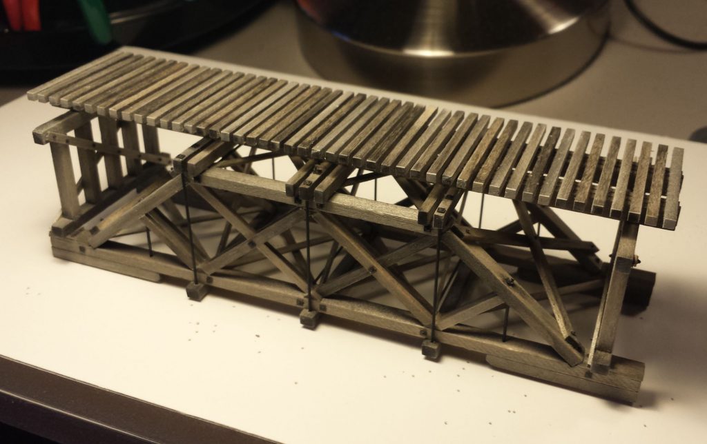
Building the deck truss bridge used standard methods at the workbench (Fig 2). Stripwood and bridge ties are from Mt. Albert Scale Lumber (now distributed by Fast Tracks), pre-stained with Micromark Bridge and Tie Stain. Having tried several glues, I use Aleene’s Tacky Glue, either standard or fast-grab variants depending on whether the workpiece is held tightly in a jig, or needs the fast-grab action. Nbw’s are from Tichy Train Group. Tension rods are 0.028” brass wire or 2.4” in HO, just slightly oversize but easier to see.
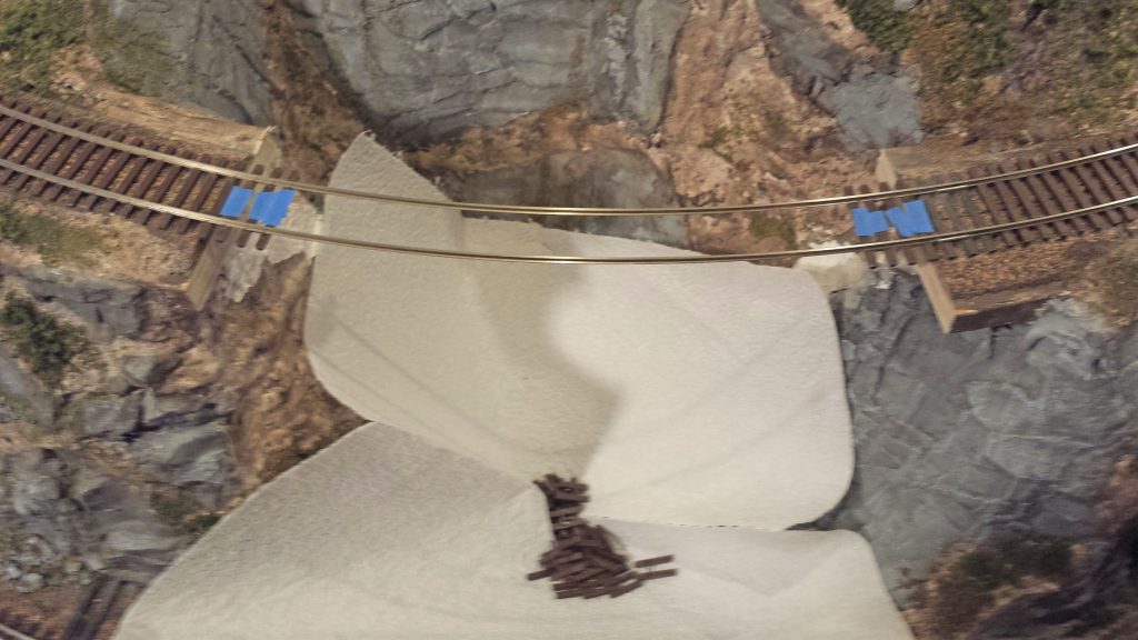
Now for the fun part! First the plywood subroadbed and cork roadbed were cut away (Fig 3) using a Zona 5” saber saw blade. The granite rock faces by the way are Cripplebush rubber rocks, which though more time-consuming to paint than plaster or resin alternatives, I am very pleased with. I presented a Skagit Valley & Whidbey NMRA clinic on their use in 2016. Next the flextrack plastic ties were removed. The blue painter’s tape marks ties that are to remain in place; these will be set in ballast on the concrete abutments.
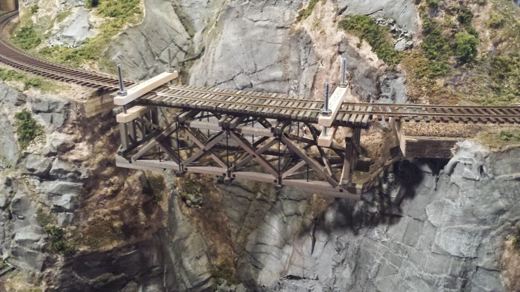
The next step, Fig 4, was to carefully clamp the pre-fabricated span to the rails. None of the clamps in my toolbox was quite right for the job, so I jury-rigged the pair seen here. Alignment is important; to get it right I drew pencil lines on the bridge ties for locating the rails.
The next step was to build the abutments below the suspended bridge span. I used basswood and artist’s mat board to simulate concrete abutments, sealing the mat board well so that it didn’t warp with subsequent applications of acrylic paint. This is the most tedious step in the sequence, requiring a number of height measurements from tie level to the pre-existing terrain. In Fig 5, the abutments are completed and ready for painting. They were blended into the existing rock terrain with Sculptamold, which was then carved with striations to match the features of the rubber rocks. All was then given a coat of white acrylic gesso. I used gesso liberally in my scenery coloring as an undercoat, to even everything out over varying materials and increase reflectance and brightness, a trick I learned from my artist son. The white stream below the span is a coat of gloss mod podge which will dry clear; this was unrelated to the bridge work and just done at the same time.
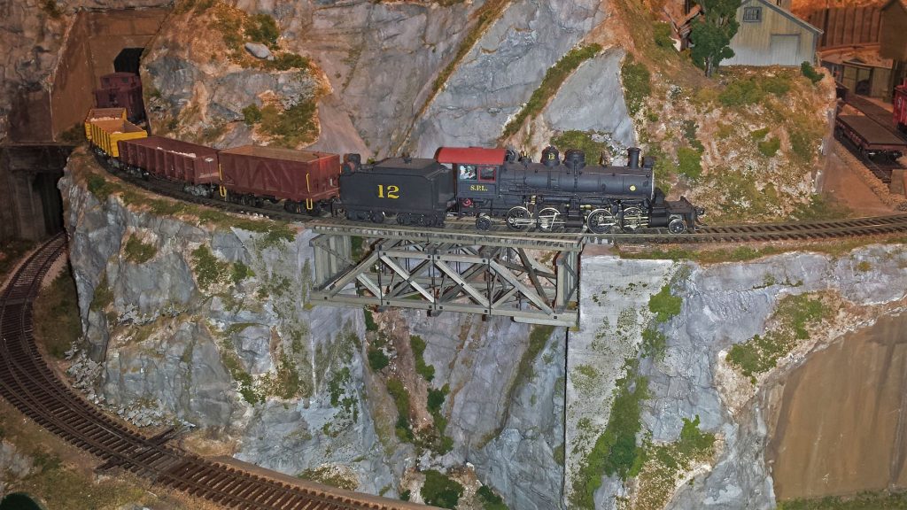
The bridge span was repositioned into place and rails spiked to the bridge ties. Guard timbers and their nbw’s were added as a final step. The completed Silver Falls Bridge is shown in Fig 6, with the CC&CRR’s heaviest loco—a 2-4-4-2—giving the bridge an axle-load test; it passed. I sized timbers and other features for an E-55 rating, or slightly lower. The abutments were weathered with India ink washes and Bragdon powders, and some simulated foliage and moss added.
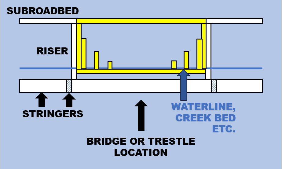
I’m not recommending that you build your bridges this way, but having boxed myself in by largely completing my scenery before tackling the bridges, it worked satisfactorily for me. There are several better ways, only one of which is illustrated in Fig 7. The idea here is, when you build your basic layout framework—stringers, risers, subroadbed—instead of keeping the subroadbed continuous across your future bridge locations as I did, construct a removable “bridge frame,” highlighted in yellow in the figure. It’s built of 1 x 3’s or 1 x 4’s or whatever your chosen lumber size is, and includes abutment and pier supports as shown. Lay your track and begin op sessions and run for years this way if you want to—but don’t complete the scenery around the bridge frame. When you’re ready to build your bridge or trestle, remove the frame, the top piece of subroadbed, and build the bridge on the frame at the bench. Reinstall the bridge frame with its completed bridge and fill in the scenery around it. Maybe on my next layout!
###
No Comments Yet