Rich Thom, photos by Rich Thom
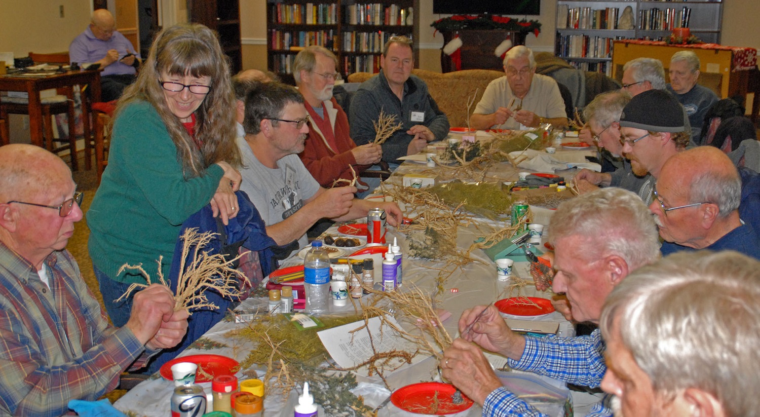
After a lot of business conducted at the overflowing swap tables, Clinic Chair Rich Blake welcomed 25 folks to the SV&W Clinic’s March meeting at the Summer Hill facility in Oak Harbor. Rich also introduced new attendee John Connelly, whom we hope will become a regular.
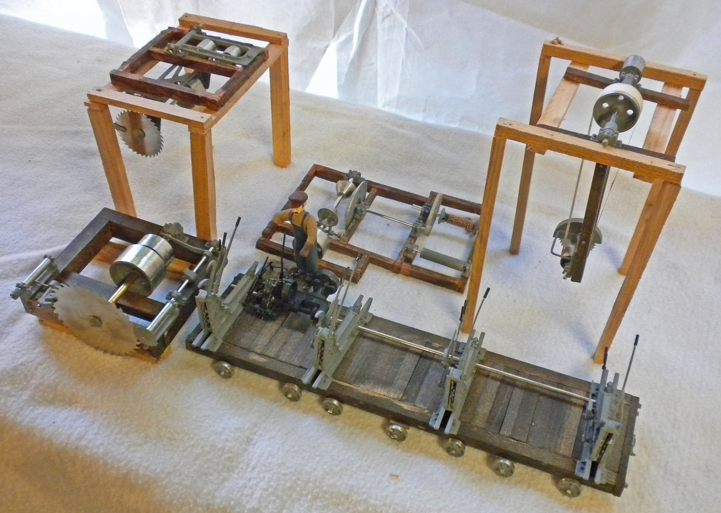
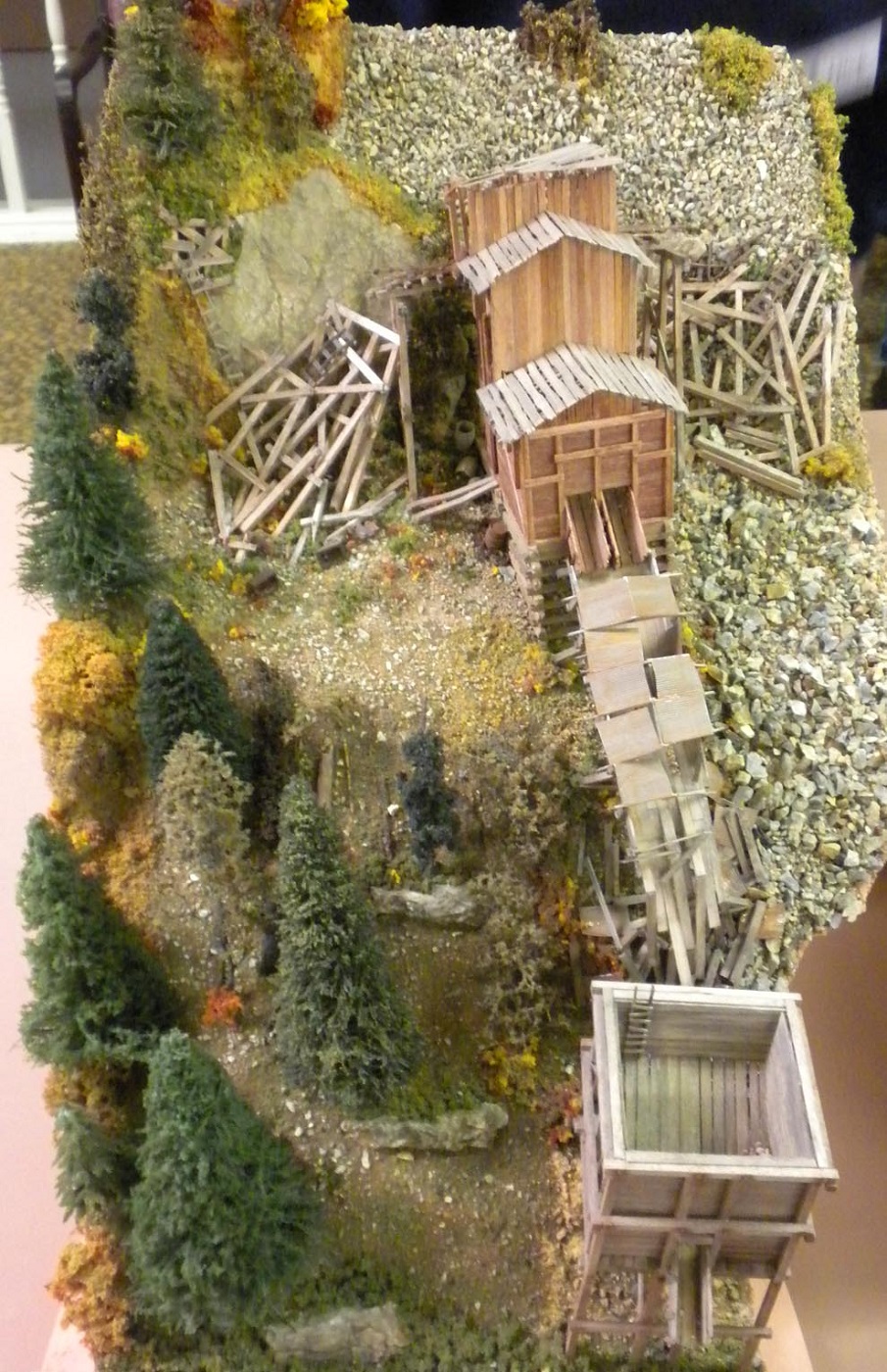
John Marshall brought his “winter project” (John has an outdoor G-scale layout in Coupeville, so winters get devoted to rolling stock and structures) for show-and-tell. He has completed a set of sawmill machinery (Fig 1) in F-scale (1:20.3) for his sawmill – a large (in more ways than one!) work-in-progress. These are kits are by Wild West Scale Model Builders, www.wildwestmodels.com. The components are identified in Figure 1. The log carriage (Fig 2) has over 150 white metal castings.

Fig 1 John Marshall’s F-Scale Mill Machinery. Clockwise from left: Lower assembly of double circular saw; upper assembly of saw (on temporary frame); log turner; cutoff saw (on temporary frame); and log carriage.
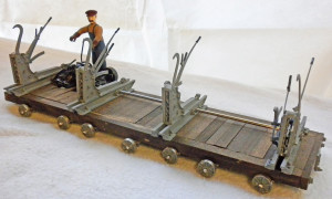
Fig 2 John Marshall’s F-Scale Log Carriage
There being no further business or pop-ups, Rich Thom gave the evening’s presentation: Viva Vapor! Steam with a Latin Beat—Modeling Inspiration on 5 Gauges. It was a “Part 2” to a talk given back in 2009, which covered different railroads in other countries.
When the last revenue steam operations ceased in the U.S, most steam enthusiasts said “that’s the end of it,” and redirected their energies to writing books, modeling, and preservation. Worldwide, though, steam was far from defunct. Some people packed their cameras intent on finding and documenting what survived beyond our borders; Rich caught this disease.
Most of the railroads in this talk used American-built locos, mostly Baldwins, and rolling stock details and operating practices evoked stateside steam railroading. We highlighted steam on 5 different gauges, in 5 countries in Central and South America:
FEGUA (IRCA)
Ferrocarriles Guatemala (Int’l. Rwys. of Central America) |
Guatemala |
3’ gauge |
Photo’d 1973, 2000 |
FES
Ferrocarril de El Salvador |
El Salvador |
3’ gauge |
1973 |
FNGB
Ferrocarril Nacional General Belgrano |
Argentina |
Meter |
1976 |
F del E Red Sur
Ferrocarriles del Estado Southern Network |
Chile |
5’6” |
1976, 1991 |
EFDTC
Estrado de Ferro Dona Teresa Cristina |
Brazil |
Meter |
1976 |
VFCO
Viacao Ferroviario Centro Oeste |
Brazil |
30″ |
1976 |
RFIRT
Red Ferro-Industrial Rio Turbio |
Argentina |
75 cm |
1988 |
We won’t take the space here to include photos for each railroad.
Bananas! — and dispelling the myth: Hauling bananas was the business of the first of tonight’s railroads. When the banana trains (called fruteras) were on the line they were strictly first class with higher priority than even timetabled passenger trains. And the huge, modern fleet of narrow gauge Mikados dwarfed even the D&RG’s roster of Mikes, dispelling the myth that steamers in Latin America were mostly decrepit hand-me-downs.
Ferrocarriles Guatemala (FEGUA) was the remnant in Guatemala of the once vast International Railways of Central America, an American-owned, 800-mile system in both Guatemala and El Salvador which reached ports on both the Atlantic and Pacific coasts, and the Mexican border. United Fruit owned 40% of IRCA, and 50% of the railroad’s income came from shipping bananas and coffee. After 1948 (when Mexico re-gauged some of its narrow gauge to standard), IRCA was the largest 3-ft gauge railroad in all of North America.
This “up and down” railroad ran from 5,000 feet at Guatemala City to sea level. Gradients were typically 3% on the Atlantic Division with a ruling gradient of 3.3%. On the Pacific Division, the steep 3.7% grade of Palin Hill was a challenge for banana trains from the Pacific Coast plantations for both steam and diesel. The line was famous for its spidery trestles.

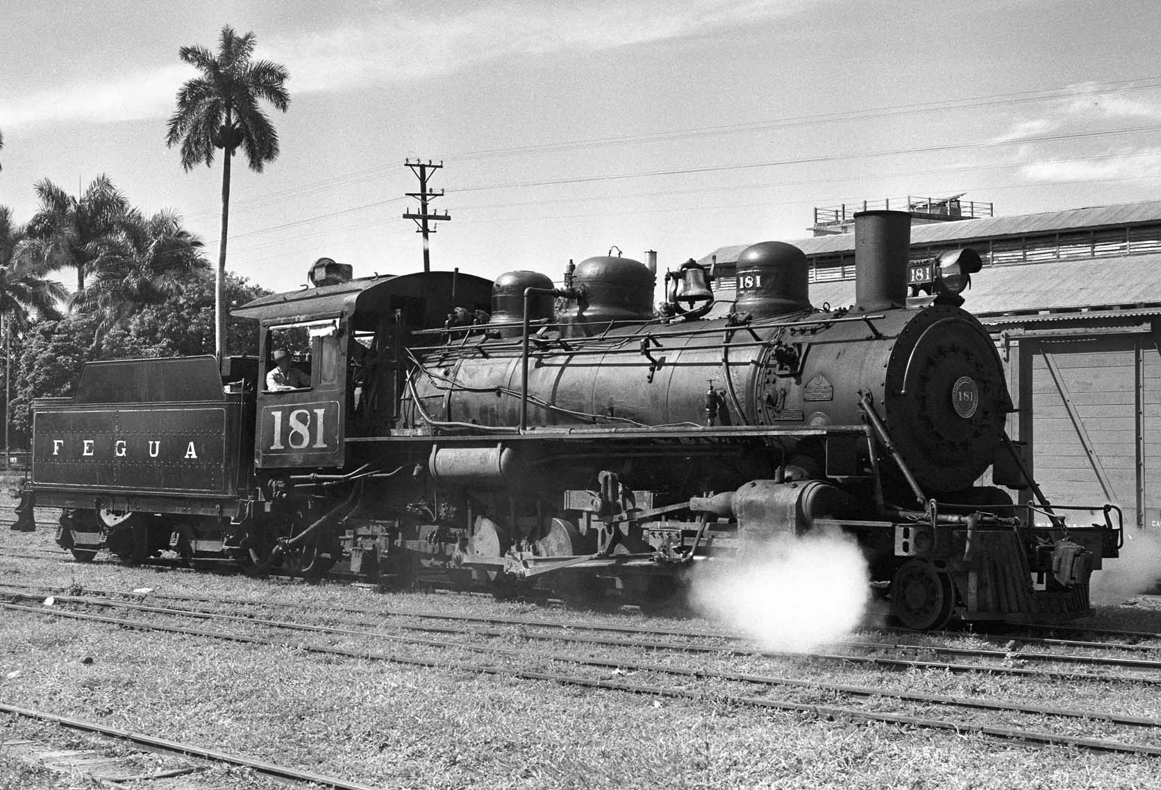
Fig 3 FEGUA 3-foot gauge 2-8-2 #181, a 1947 Baldwin product, readies as helper up steep Palin Hill in Guatemala (1973)
IRCA, and the later FEGUA, had a very large roster of steam locos from builders Baldwin, Porter, and Krupp, with Baldwins dominating. In its later days, mostly 2-8-2 Mikes, smaller Consolidations, and GE diesels were used. A large Baldwin order of 32 identical Mikes, including #181 shown above, was delivered during 1946-48. The IRCA had 57 Mikes altogether of basically the same design.
The Ferrocarril de El Salvador (FES) was always the down-on-its-luck cousin to the IRCA, never a part of the much larger railroad. The first railroad in El Salvador, the smallest of the Central America republics, was built between the coast and Sonsonate in 1881-2. Another 3’ gauge line was constructed from Santa Ana to the capital San Salvador, and in 1895 an English firm combined the two lines under the present name. Despite the British ownership, most of the equipment was American. The youngest steam engine on the property dated from 1926, and most of the rolling stock was of 1880-90’s vintage. Some locos and cars saw service in Hawaii.
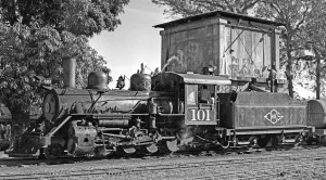
Fig 4 FES 2-8-0 #101, a 1925 Baldwin, simmers at Sitio del Nino, the only junction on the 3’ gauge Ferrocarril de El Salvador (1973)
Not worth the trouble: Rich was sometimes asked, “why are you using your sparse vacation time to go ‘down there’ to photograph steam, when it’s all just small stuff?” Well, in truth, there was nothing even close to our American and Canadian monsters, but there were some large locos with respect to the track gauges on which they ran.
The Ferrocarril Nacional General Belgrano (FNGB) in Argentina grouped together all the meter gauge railroads in this multi-gauge country. Tucuman in the far northwest was the hotbed, and Rich got there in 1976. Baldwin had filled an order in 1921 for 85 locos, its largest foreign order of that year, a mix of Pacific, Mountain, and Santa Fe types. Remarkably, most of them were still the mainstay of the loco roster in 1976, although a few diesels had intruded. Otherwise, it was entirely a steam show—one of the last in the western hemisphere. Chile’s Ferrocarriles del Estado Red Sur (F del E) was another destination for steam in the 70’s. Chile, a narrow north-to-south country, has a railway system to match. A single main line runs north out of the capital Santiago, and another south. The southern system — the broad gauge 5’ 6” Red Sur — is by far the most important and active. Once all-steam territory, Red Sur tracks weren’t overwhelmed by diesels but by electrification. By the end of 1972 wires were up all the way to Concepcion. Steam retreated south and held on, and as late as the early 70’s there were approximately 200 steam engines working. Temuco boasted the largest allocation with 50 engines, and was the place to go: Rich visited in 1976. Traffic was hauled mostly by Baldwin and Mitsubishi 4-8-2’s, Alco and Montreal Mikados, and German-built Moguls.
The Estrada de Ferro Dona Teresa Cristina (EFDTC), an isolated meter-gauge operation in southeast Brazil was arguably the most exciting big steam rail operation in all of South America. The line existed to haul low-grade coal from Serra do Mar to the port of Imbituba. In the early seventies, five 1000-ton coal trains operated daily on weekdays. What might have been a ho-hum operation was instead spectacular because of the motive power. 1925 Baldwin Pacifics — left over from a long-abandoned passenger service — and stocky Alco Mikados held down the less-stressing duties. The pride of the EFDTC, though, was a fleet of Baldwin and Alco 2-10-4’s built 1940-47. The sight and sound of these wholly American heavy-haulers on the point of a coal train heading for the Atlantic port was stunning.
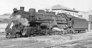
Fig 5 EFDTC meter-gauge Texas-type #301, a Baldwin product of 1940, awaits coal-train duty at Tuburao in 1976
Bachmann slept here! Bachmann has produced in several scales lovely old Baldwin locos. Incredibly, there was a railroad — Brazil’s Viacao Ferroviario Centro Oeste (VFCO) — where locos survived into the ‘70’s that were spitting images of some of these models. Sao Joao del Rei was the main terminal and shop town for the 121 miles of 2’ 6” track of the VFCO. The line served primarily as a feeder to two broader-gauge lines. Gondolas of limestone for an on-line cement plant and box cars of cement constituted most of the tonnage.
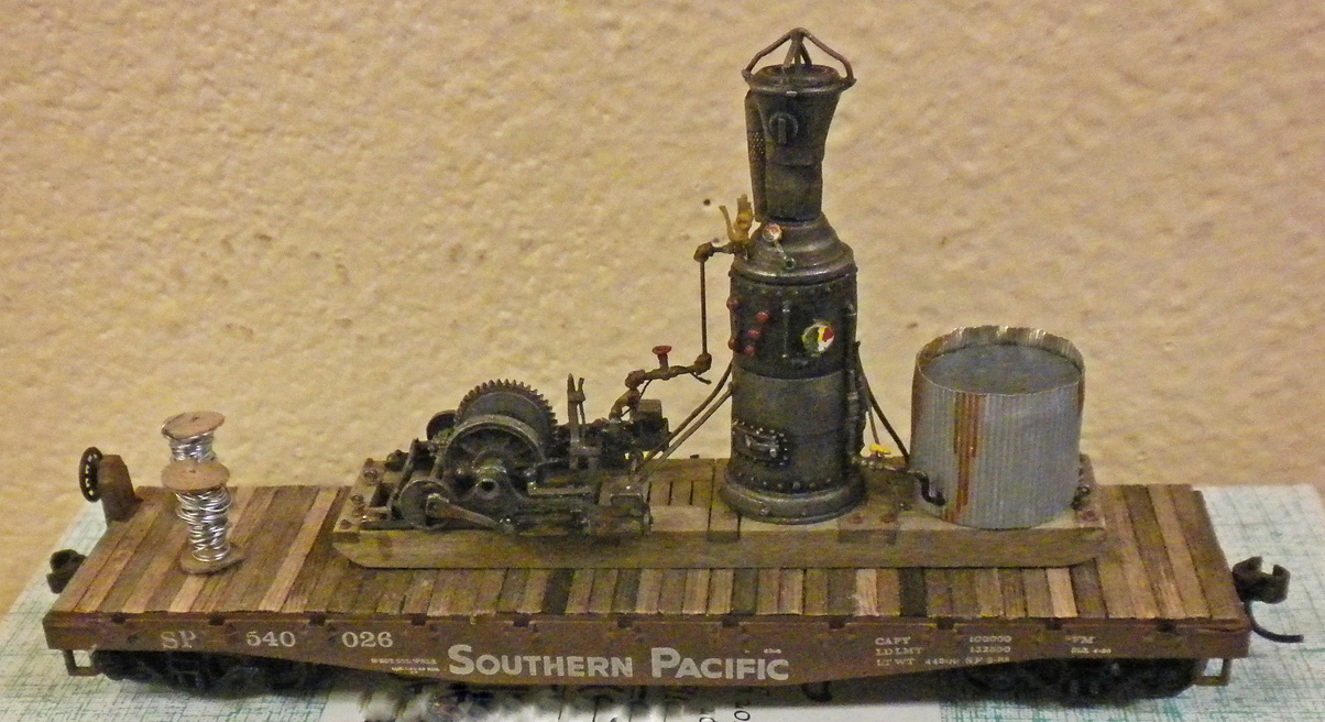
When Rich visited in 1976, passenger service was still operating as mixed trains. All were hauled by the VFCO‘s magnificent fleet of all-Baldwin locos, the oldest (in 1976) dating from 1889. Take a look at this website photo of Bachmann’s On30 4-4-0:
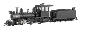
Fig 6 Bachmann On30 4-4-0
and then compare it to the “real thing” in Sao Jao del Rei’s yard. Note the steam dome snugged up to cab; single air pump; bell, sand dome, and copper-topped stack all in the same positions; Pyle generator just in back of the headlight; slide valves; and outside frames. The Bachmann model is coal-fired, whereas the VFCO loco is oil, and the front pilots are different. Otherwise Baldwin did a great job of copying the Bachmann product!
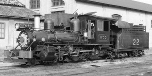
Fig 7 A rarity indeed: 4-4-0 #22 of the Viacao Ferroviario Centro Oeste works the yard at Sao Jao del Rei, about 150 miles north of Rio de Janeiro
At the end of the world, the biggest little 2-10-2’s ever: The talk concluded with the Red Ferro-Industrial Rio Turbio (RFIRT) a 75-cm gauge railroad from Rio Gallegos on the Atlantic coast to Rio Turbio near the Chilean border. This line was located in the extreme southern portion of mainland Argentina and its business was to haul coal to the port. The motive power was diminutive 2-10-2’s, all built by Mitsubishi. The locos were so small a man of modest height could peer into the cab window. They were extensively modified by the steam innovator Ingeniero Porta to become some of the most efficient steam locomotives on the planet at the end of steam. They were so successful that Porta proposed enormous (for 75 cm gauge) and efficient locos such as a 0-12-12-2—which became very close to being built. Such innovative locos never materialized but it is an interesting footnote to worldwide steam development that the very last of high-efficiency, modern steam locos would see service on — of all places — the most remote, and southerly railway in the world.