By David Yadock
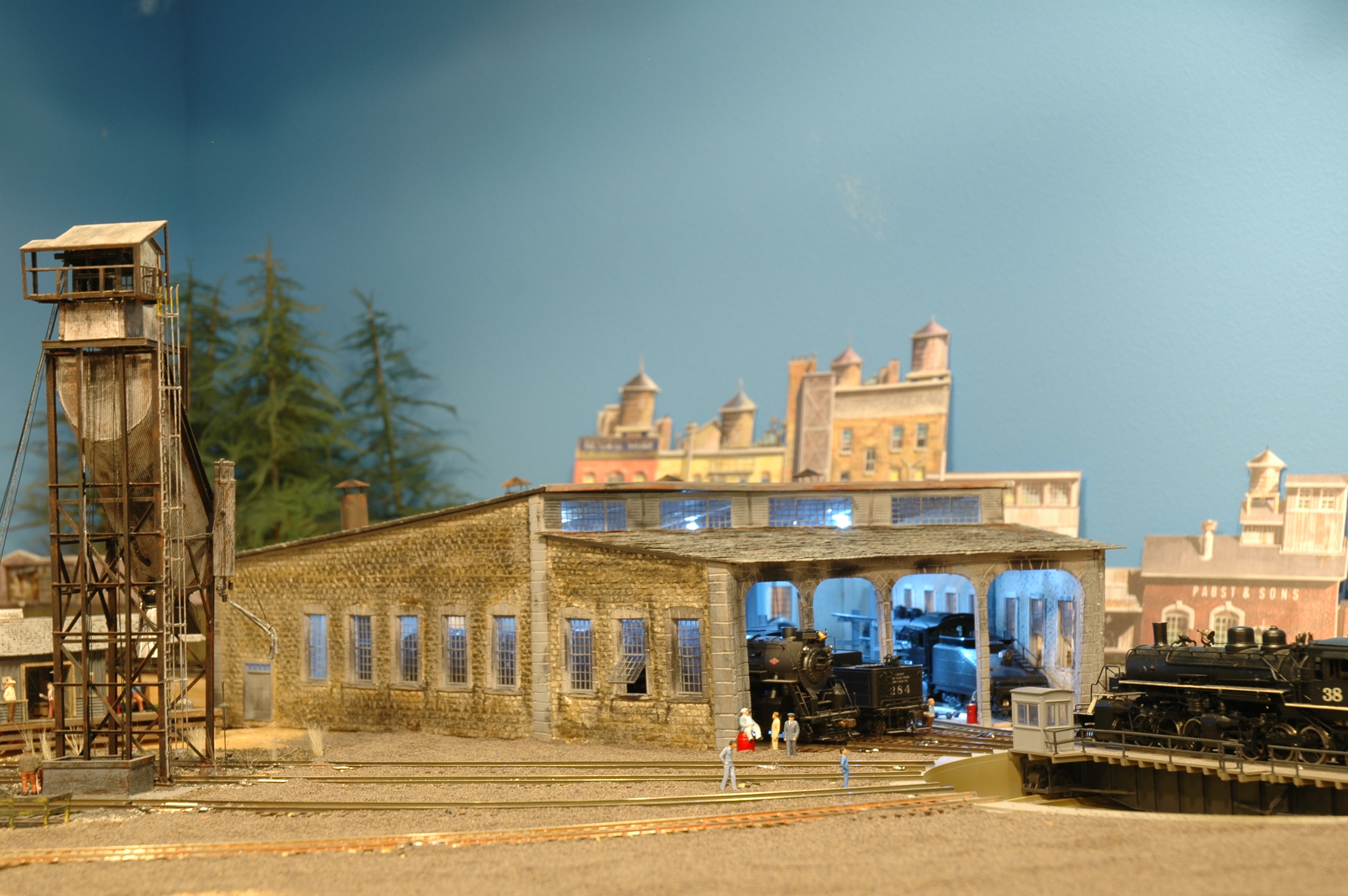
Photo 1 – Background needing buildings
I was needing to make background buildings for a section of my HO scale layout. (See Photo 1.) I had placed some of the Walthers paper cutout buildings but I found them unacceptable. They looked unrealistic where they were located and how they were positioned. The scene really needs depth and detail! The major issue is that the area only has approximately an inch of space between the wall and the railroad track right-of-way. Additionally, there are several lineal feet of wall to cover with the appropriate background/backdrop. I envisioned the scene to be a gritty industrial area with the foreground containing my steam engine facilities.
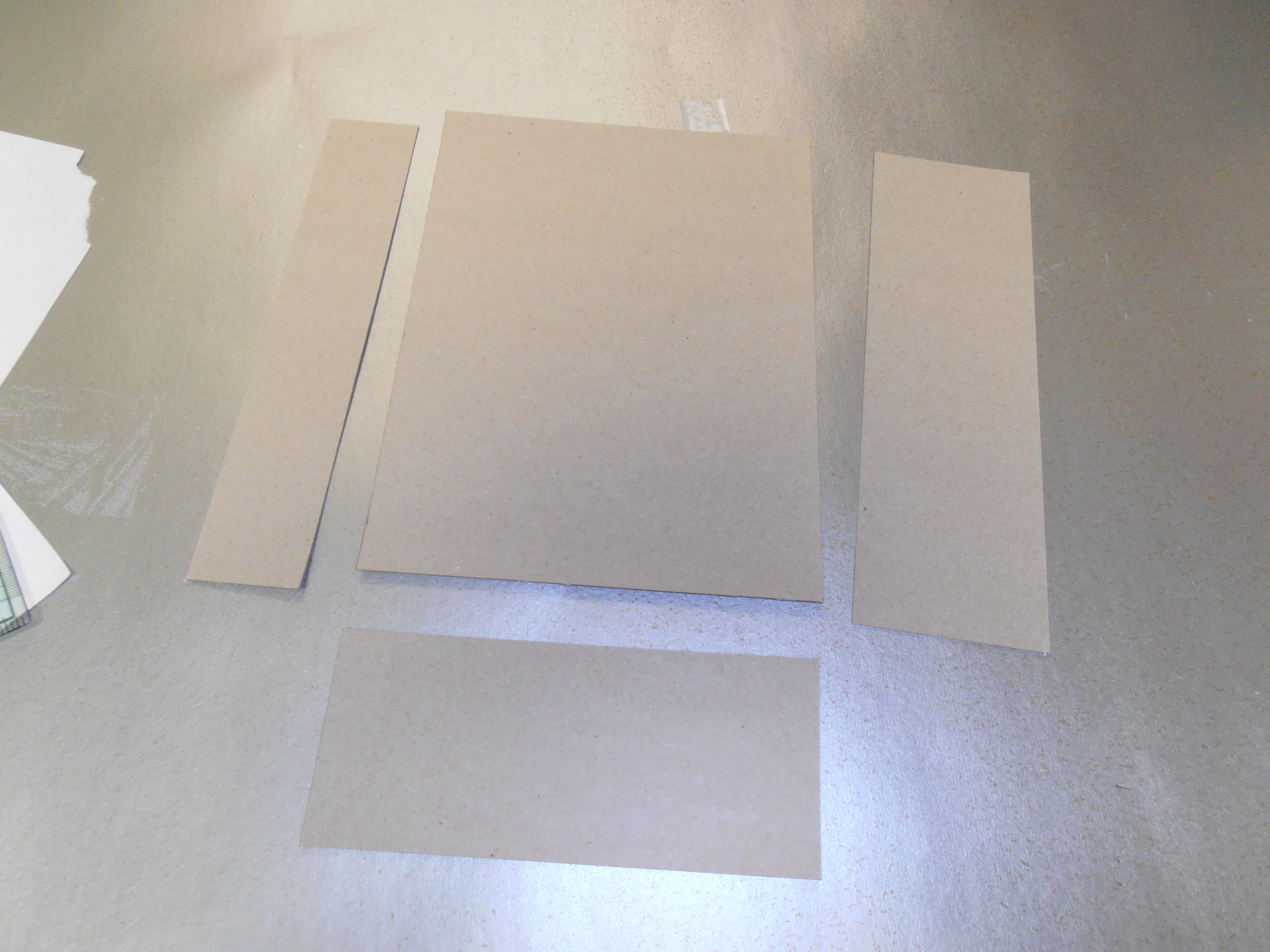
Photo 2 – Cardboard cut to size with a straightedge and sharp knife
Please note, with background construction one must remember that the buildings are just that, a general background (building or otherwise) to be used to direct the observer’s attention away from a blank wall or other offending item. Modelers need to be sneaky when constructing their layout since every standard layout room has many offending characteristics to it. The trick is hiding the problem areas while creating a functional scene. This process makes for some interesting challenges for scenery construction.
I decided to go with my usual “old school” approach to the construction of the buildings. Yes, the youngsters in the crowd (I know there are a few here in the 4th Division) will scoff at my methods but they do work and the structures are really inexpensive to build. Most of the buildings cost well under $10 to construct. The base material I use for these buildings is cardboard from cereal boxes. This is a very cheap source for a nice smooth substrate for attaching the paper covering.
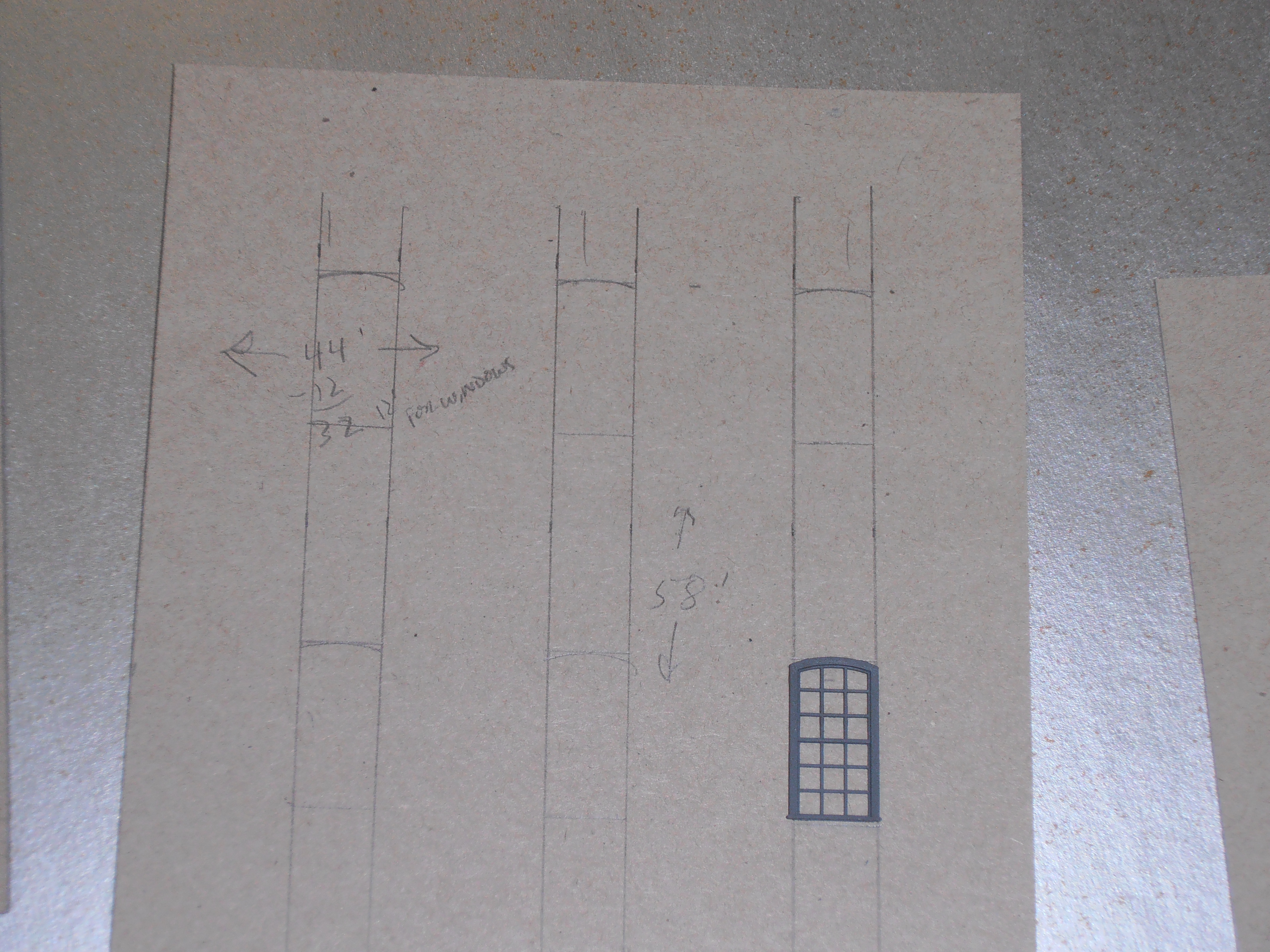
Photo 3 – Windows and doors marked on cardboard
One thing I have found is that the cardboard needs to be braced for extra stability. I brace the cardboard with ¼” square balsa strip wood. Eighth inch square basswood can be used as a substitute but is more expensive than the balsa. (I have used both with great success.) Once the walls are braced, there is a nice stable surface for adhering the wall coverings. Bracing also allows for some interior details and lighting to be added or attached. Please note that this article is a general overview to show how to construct background buildings. Door and window placement is up to the modeler and in some cases doors and foundation detail can be left off of the model depending on how and where the model is located in the scene.
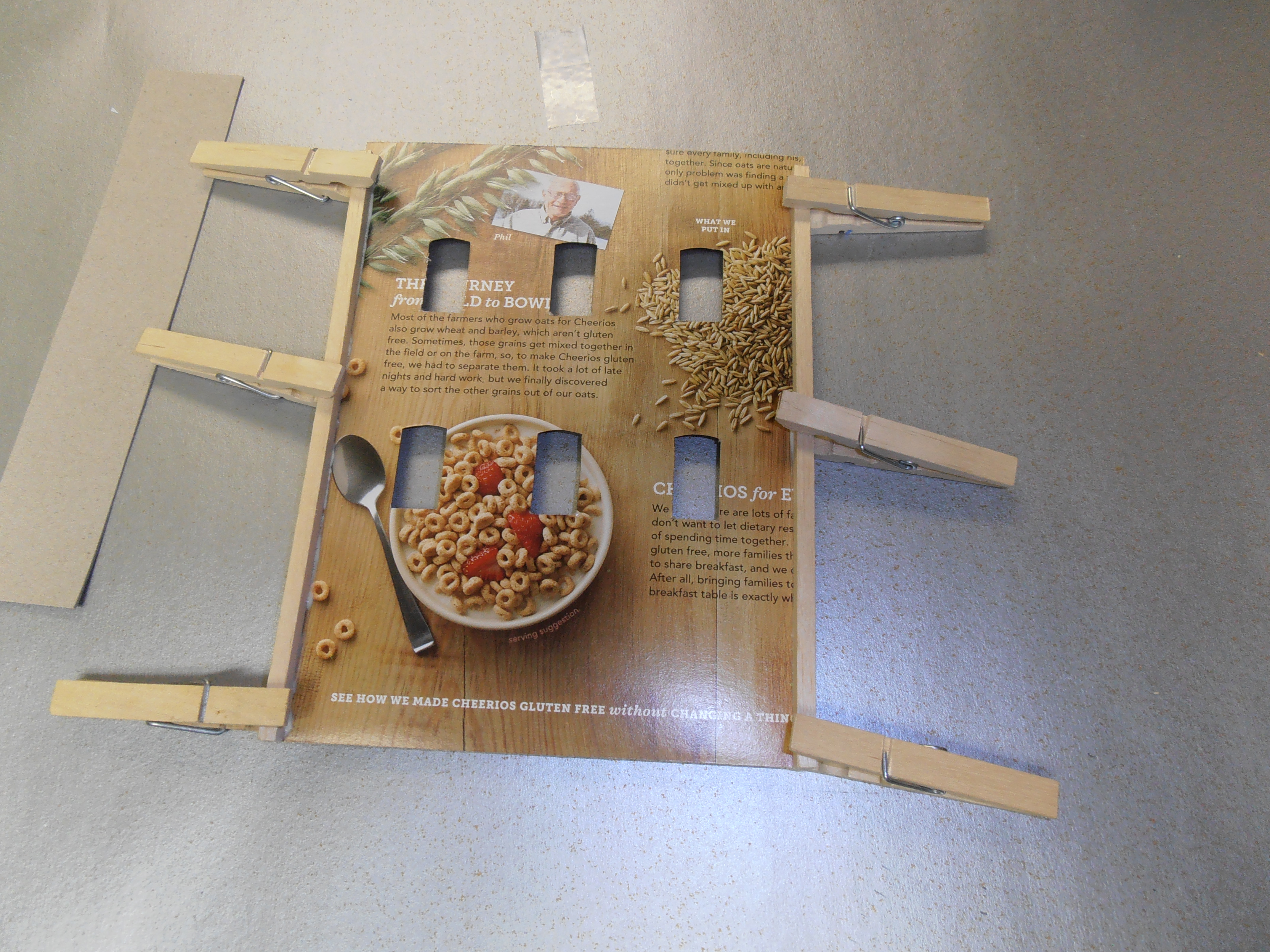
Photo 5 – Balsa bracing added to back side of wall
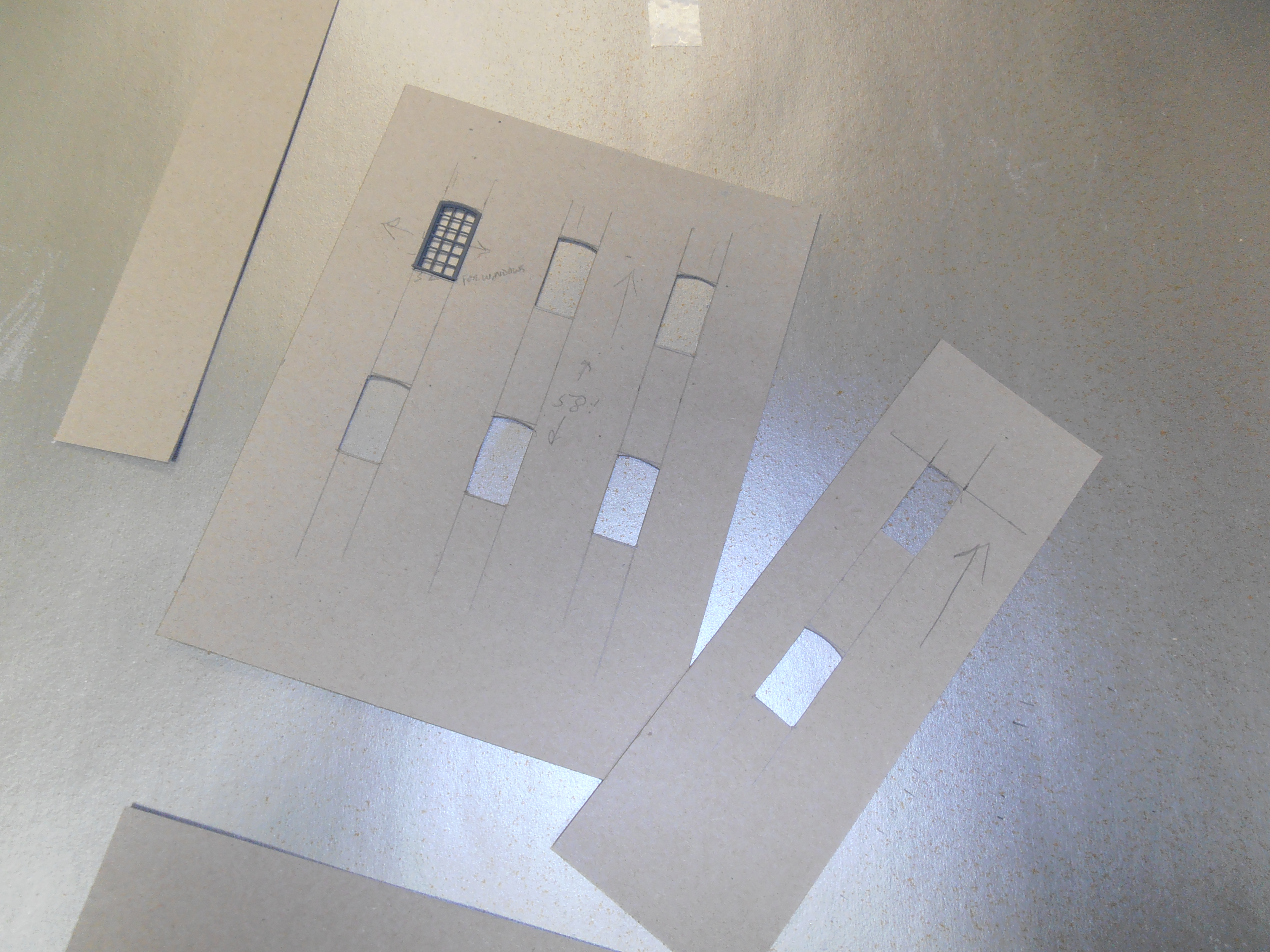
Photo 4 – Window and door holes cut out
One item that I have found very useful is my Evan Design software for making building siding materials out of paper. This trusty software prints various wall coverings (brick, stone, metal, and wood siding) from just standard printer paper.
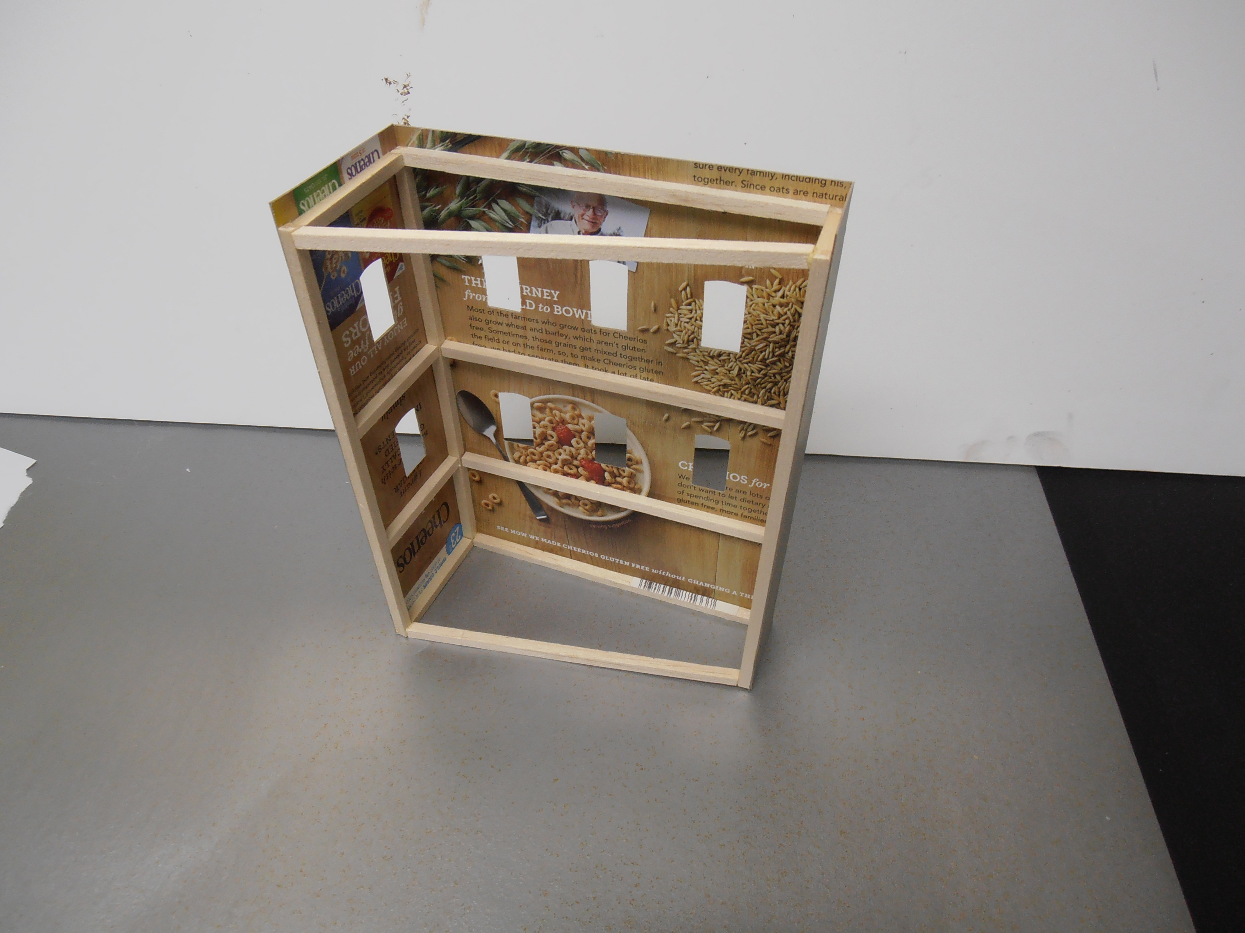
Photo 6 – Side walls attached to front wall
I first cut the cardboard to size with a straightedge and sharp X-Acto knife. (See Photo 2.) I then mark out where windows and doors are to be located. This can be drawn directly onto the cardboard. (See Photo 3.) Care must be taken to make sure the holes are the correct size and lined up properly. Once done I cut out the window and door holes. (See Photo 4.) When that is completed I add the ¼” square balsa bracing to the back side of the wall. I use Elmer’s wood glue for this operation. (See Photo 5.) The side walls can be constructed in the same manner as the front wall. I usually attach the side walls to the front wall prior to the addition of any exterior paper covering – doing this will help hide any corner imperfections. (See Photo 6.) If the sides have some special architectural features then you may want to wait to glue them to the building front. Remember to be aware of building orientation during all of these steps. It sometimes helps to mark the building orientation by drawing arrows denoting which is the top and bottom on the front of the building, as seen in Photo 4. Denoting left from right is also very helpful. Some of my buildings are constructed to allow for a slight angle when placed against the wall. This helps hide the joint between the wall and the backdrop building especially when several buildings are placed together against the wall. (See Photo 7.)
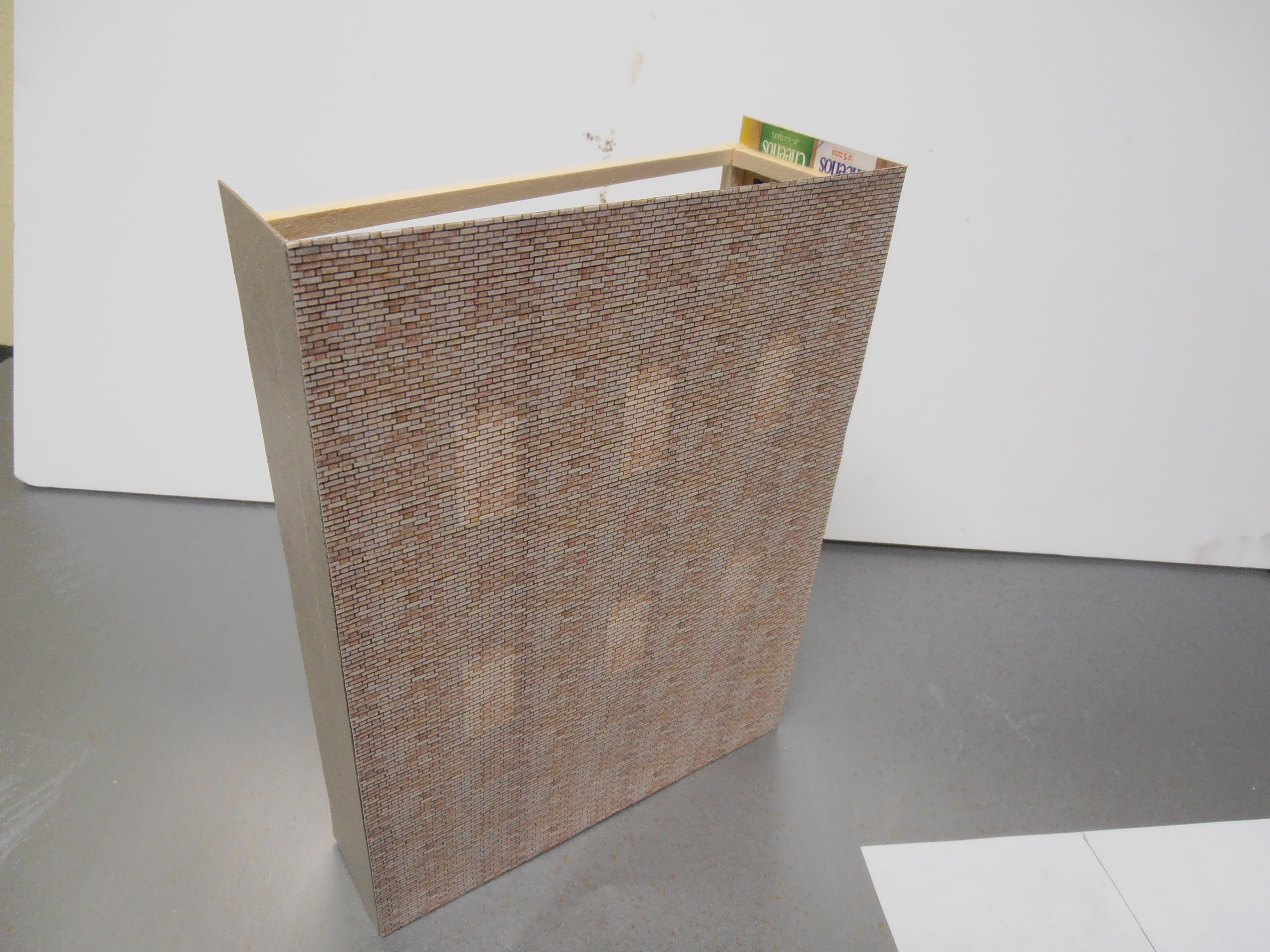
Photo 7 – Slight angle to hide joint between wall and backdrop building
Once the glue is dry I then add some printed cut stone paper to represent the foundation wall at the building base. A two or four stone course height is adequate to represent a normal foundation. This is attached using rubber cement. (See Photo 8.) I coat the cardboard area of the foundation wall and also coat the back of the stone foundation paper. The paper is attached to the building wall when the rubber cement is dry. This method works well and allows for mistakes. If an error occurs you just have to peel the paper off the structure and apply some new paper. A single sheet of this printed stone paper can go a very long way for building foundations.
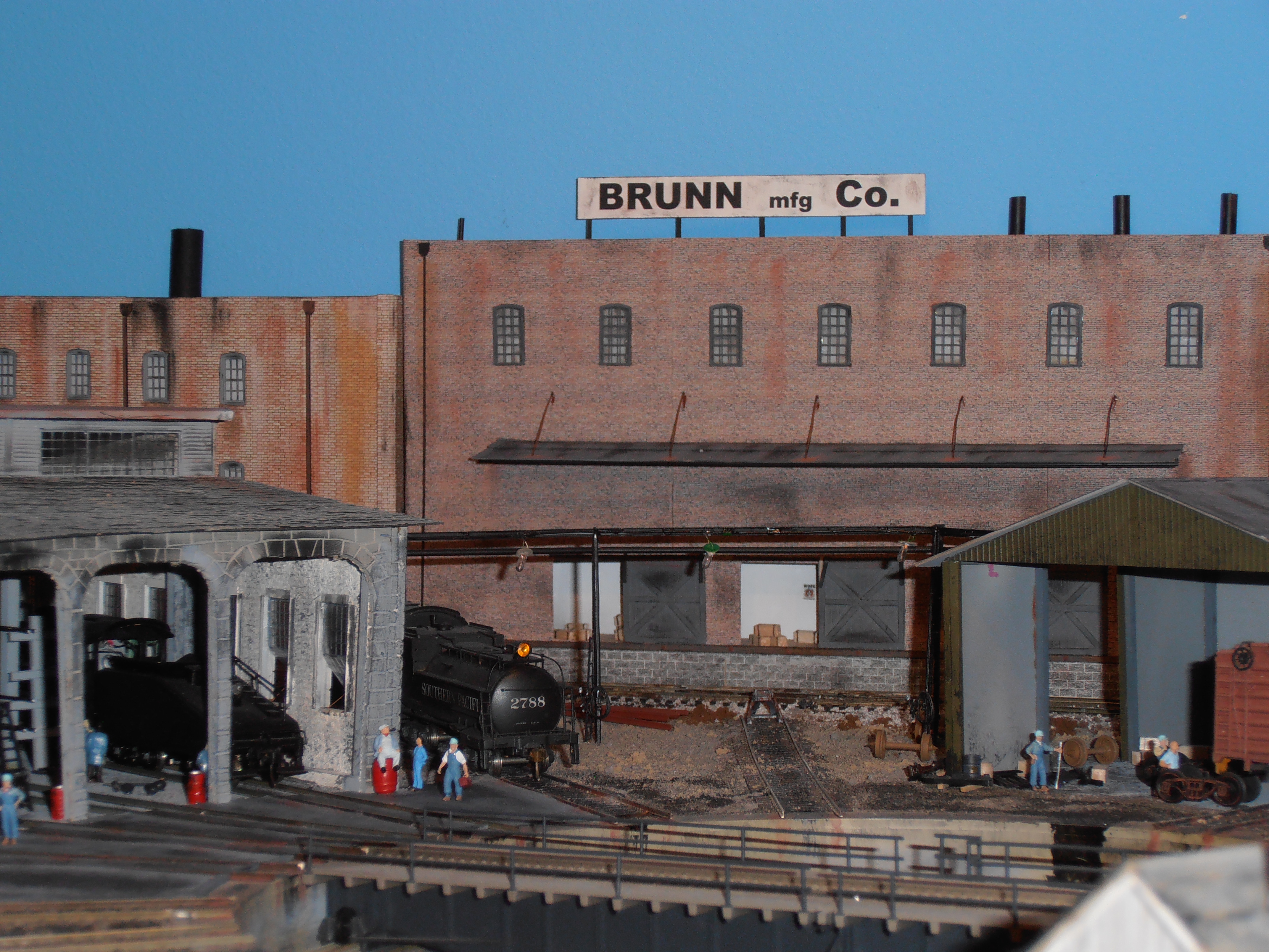
Photo 8 – Foundation wall added to base of building
The main structural material I use for a lot of my factories and warehouses is brick paper although wood, cinder block, stone, or even sheet metal can be used. (See Photo 9.) The brick printed paper is a good material since it visually adds texture to the building even though the exterior walls are flat. The Evan Design software has quite a few brick variations so you don’t end up with all the buildings looking the same. The software has designs for older brick or more distressed brick found on buildings that have not been properly maintained. For increased interest to a brick building string courses and pilasters can be added to the structure (I’ll explain how to do this later in the article). This helps break up a very tall building or a monotonous long wall.
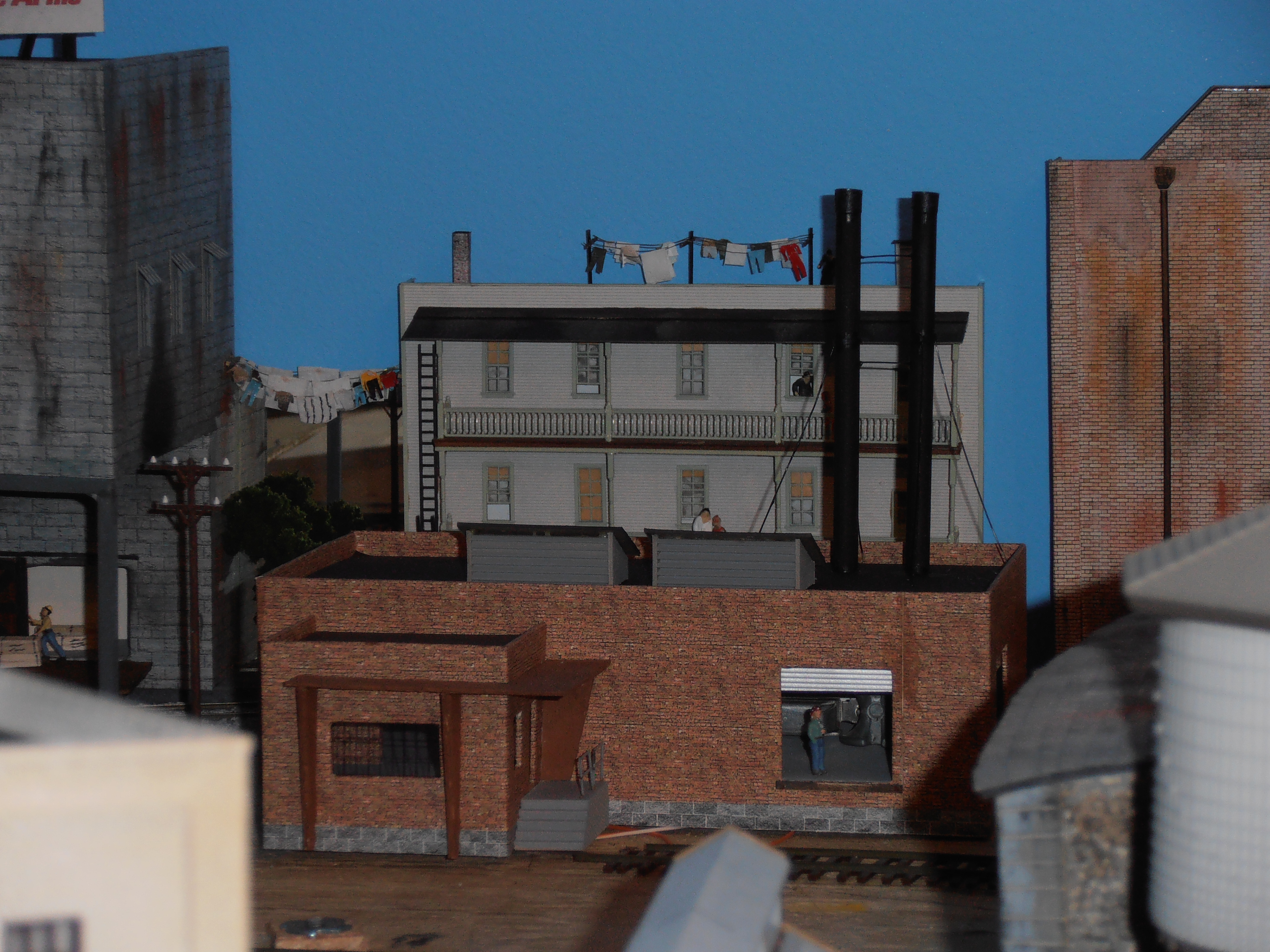
Photo 9 – Brick paper is used the most
Once the correct siding material has been selected and printed the next step is to apply the rubber cement to the siding material and to the cardboard of the building structure. It only takes a few minutes for the cement to dry. It is best to do this in a well ventilated area. The next step is to place the printed paper onto the building. You can use a clean sheet of printer paper to lie between the printed brick paper and the building structure – this will function as a barrier to the rubber cement. The barrier will allow proper alignment of the printed paper. Once the printed paper is positioned properly you can slowly slide the clean printer paper away. Doing so allows a controlled application of the paper to the building. Again, if an error happens it is not the end of the world! The printed paper can simply be peeled away and replaced.
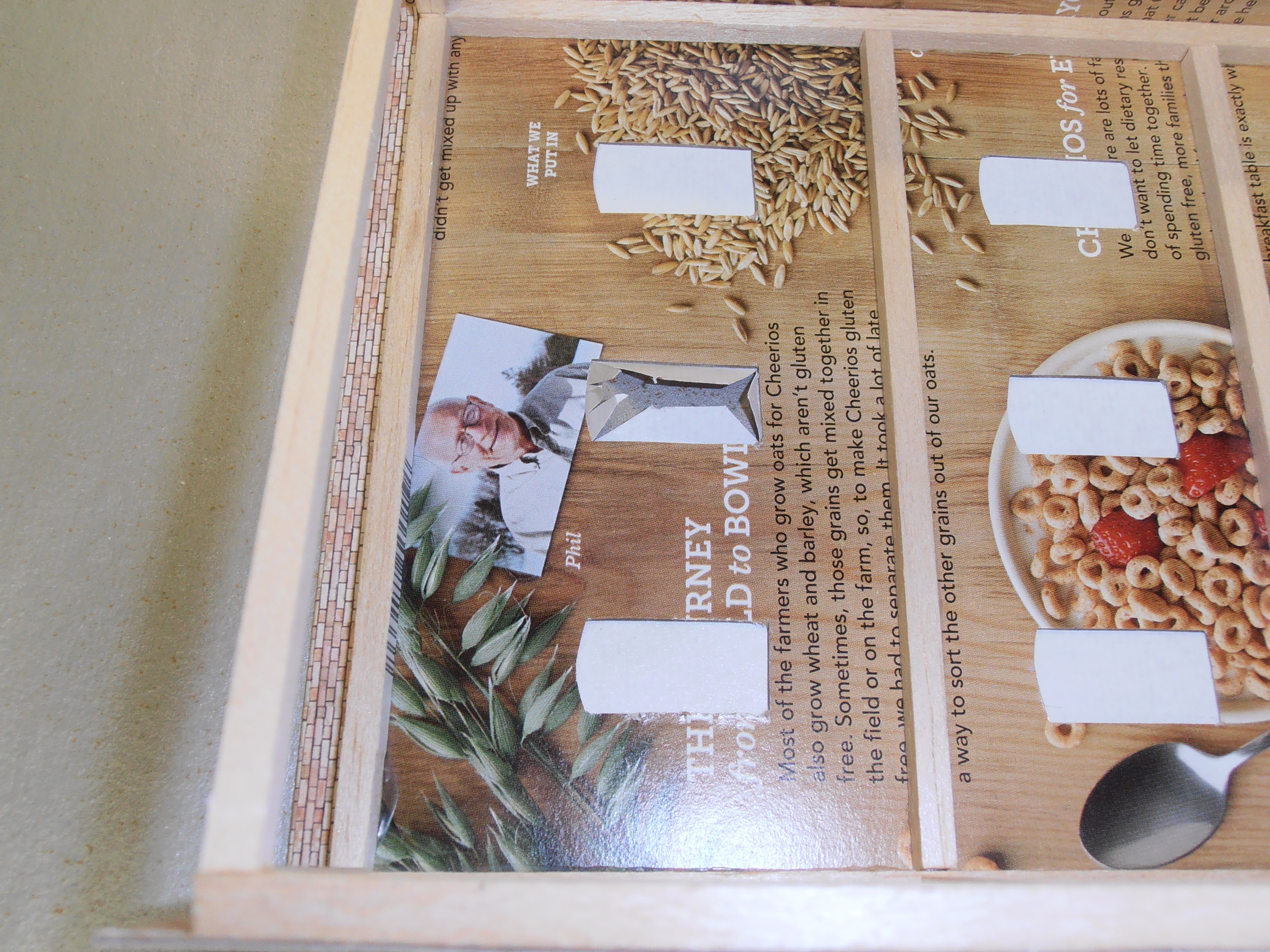
Photo 10 – Window and door holes opened up
Once all the printed brick paper is installed onto the building you can open up the window and door holes. (See Photo 10.) Simply poke your X-Acto knife through the window or door hole. Make an “X” cut so that the cuts extend to each corner of the hole. Once done you have four triangles that can be folded back onto the backside of the building. This excess can be glued to the backside using either rubber cement or Elmers glue. This creates a nice exterior trim if you use interior surface mount windows or doors. (See Photo 11.)
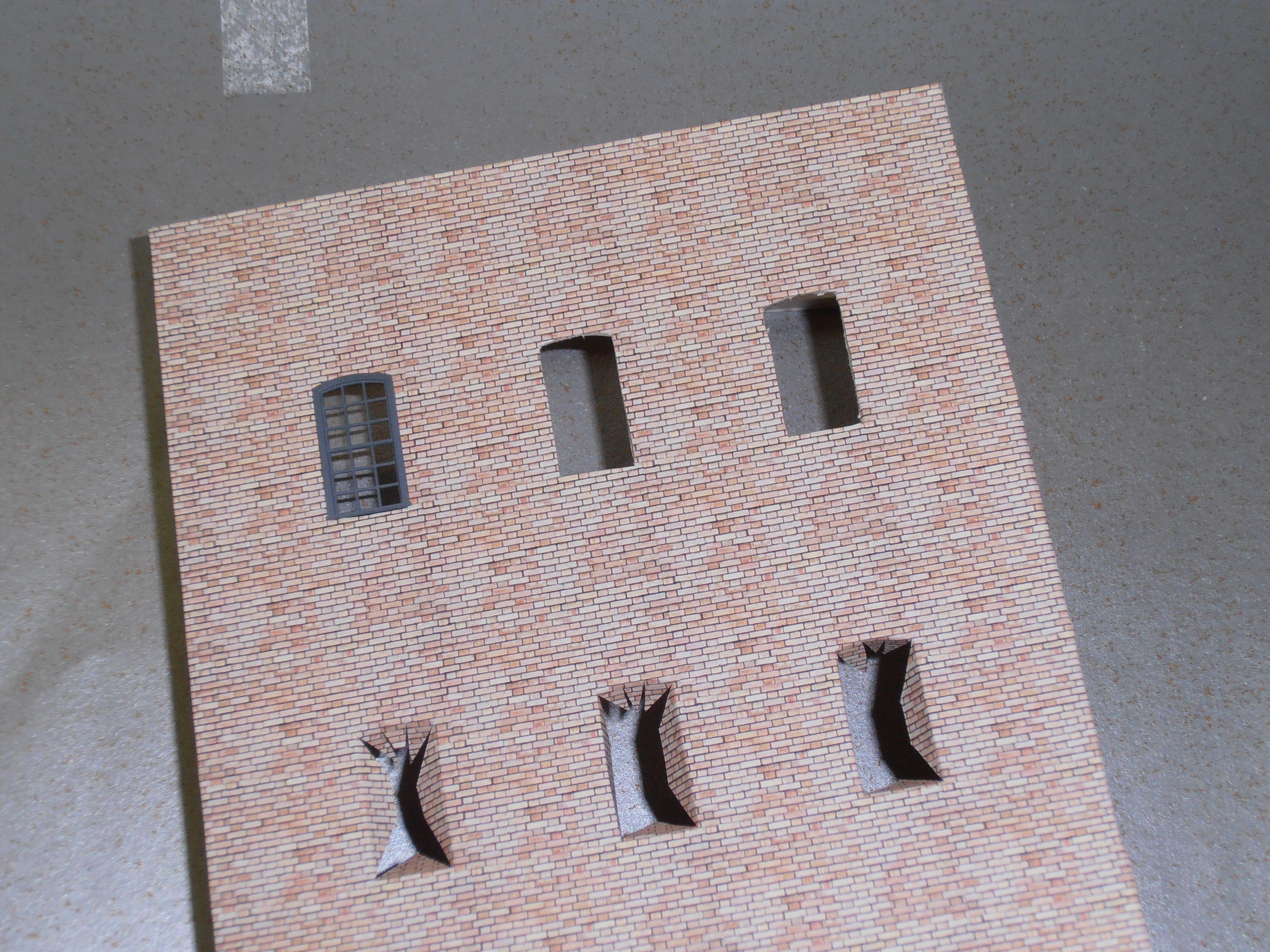
Photo 11 – Triangles folded back onto building backside
Big buildings create a special problem. Since the Evans software only allows for standard size paper to be printed one must join several “pages” of siding material together to cover a large structure. This creates a joint/seam, either vertical or horizontal that must be hidden. There are several options to use when hiding a joint. Rain downspouts are an excellent method for hiding vertical joints and create a 3-D shadow line on the building. Using small diameter, stiff wire is a good way of representing a downspout. When painted black with some rust accents it will fill the bill and hide the offending joint. Careful placement of the joint will help make the locations of the rain downspouts look plausible. Pilasters are another method – these are the vertical buttresses (especially in brick structures) that protrude from a building side sometimes to the thickness of several courses of brick. Creating pilasters is very easy. Simply cut a strip of cardboard that is one to two feet wide and the height of the building. Using rubber cement, attach some brick paper to one side of it. Then apply some Elmer’s glue to the other side and place it directly onto and over the offending building joint. This will cover the joint on the building façade. If you want to make it even easier you can make concrete pilasters. A gray painted cardboard strip can be glued to the building instead of the brick paper one. This type adds a nice contrast to the building front. It also helps create a shadow line to give the building front some depth. Photo 9 shows examples of building end pilasters and rain downspouts (note the brick structure on right).
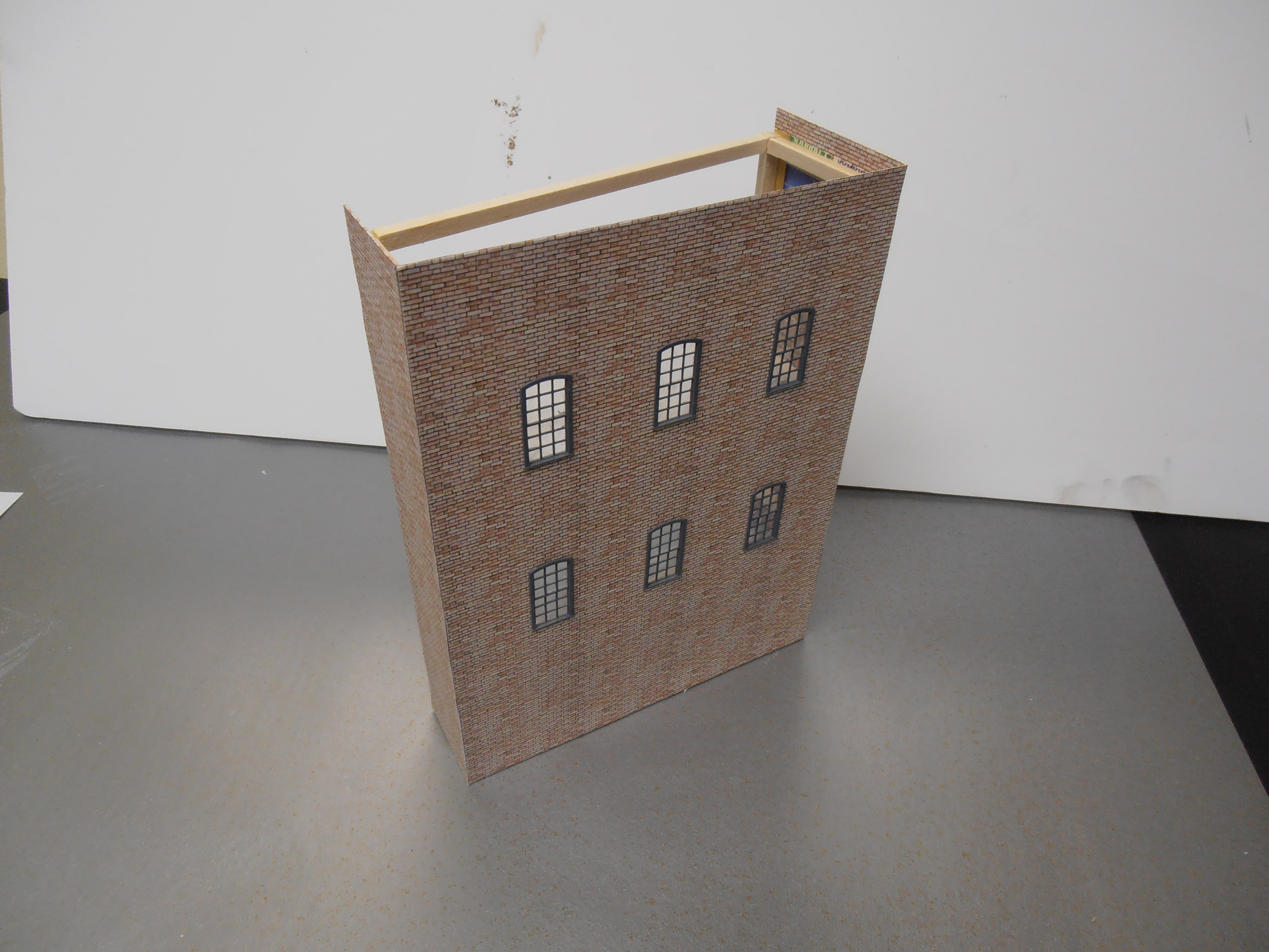
Photo 12 – Windows and doors added
Horizontal seams are more difficult to hide but if using brick paper are very difficult to spot if the paper is lined up properly. Yes, horizontal downspouts do exist but only in very short runs so one must find other methods to hide an obvious seam. If there is an offending seam that must be hidden you can add a horizontal beam by using the same approach as the vertical pilaster method just described. These can be added at regular intervals along the building to create the effect of extra support for each story of the building. Another way of hiding a seam is to break it up by placing some exposed piping that may run along the outside of the building. Adding outside vents or mechanicals will also hide the seam. Placing the seam along a series of windows can distract the casual observer and make a seam virtually impossible to see. One must remember that these are background buildings and will be some distance from direct close inspection by the layout viewer, so an offending seam may not be visible when installed on the layout.
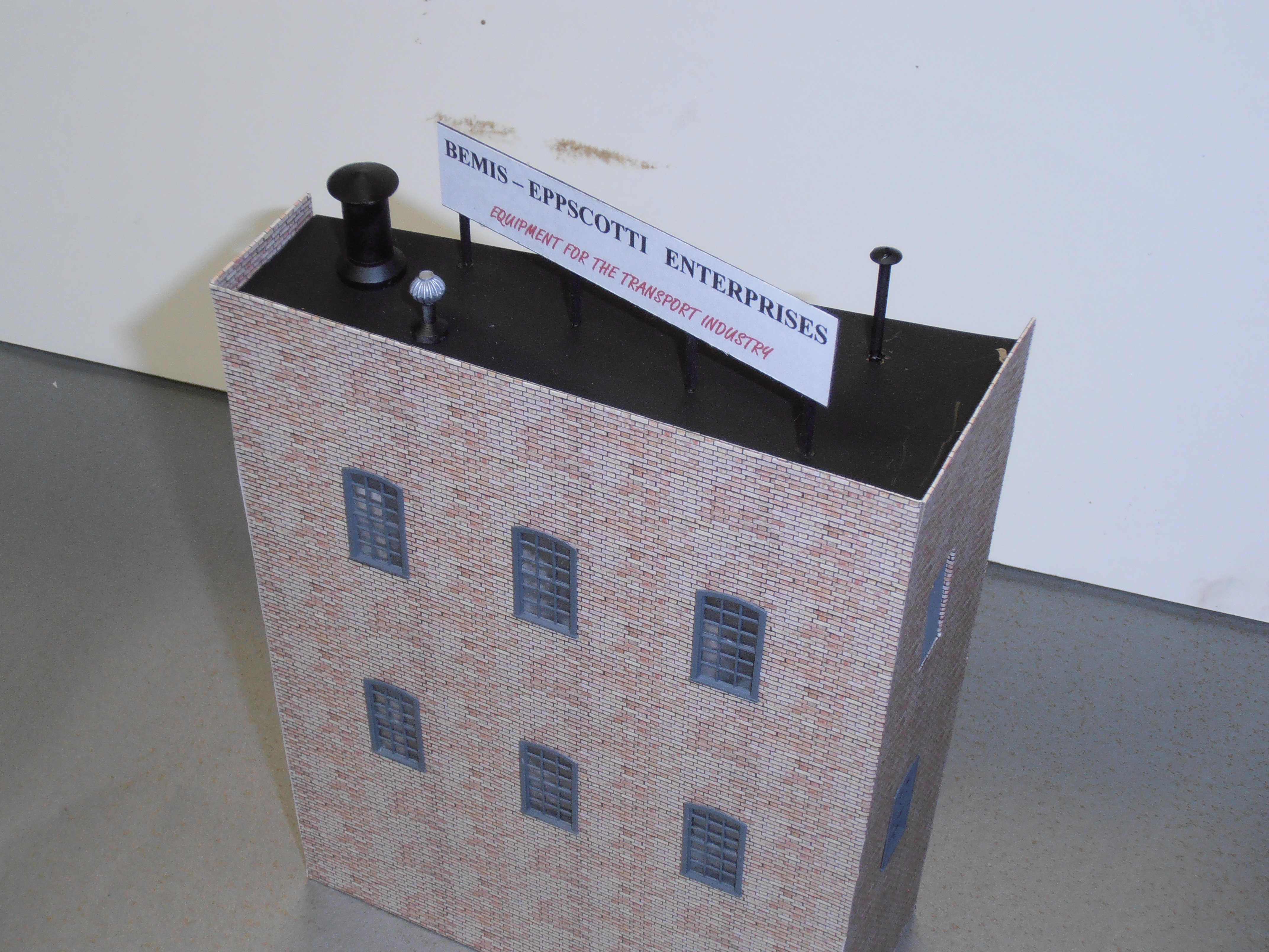
Photo 13 – Details added to roof exterior
Once the siding material has been added to the building structure and completed, you can now add windows and doors. (See Photo 12.) I prefer using commercially obtained window and door castings. They are much more uniform in size and easier to install. I use either Tichy or Grandt Line. They are reasonably priced and have a good level of detail. They are very easy to install into the holes previously made into the cardboard building front. Make sure they are painted and have their glazing installed prior to installing on the building. If the windows need shades or other treatment now is the time to add them!
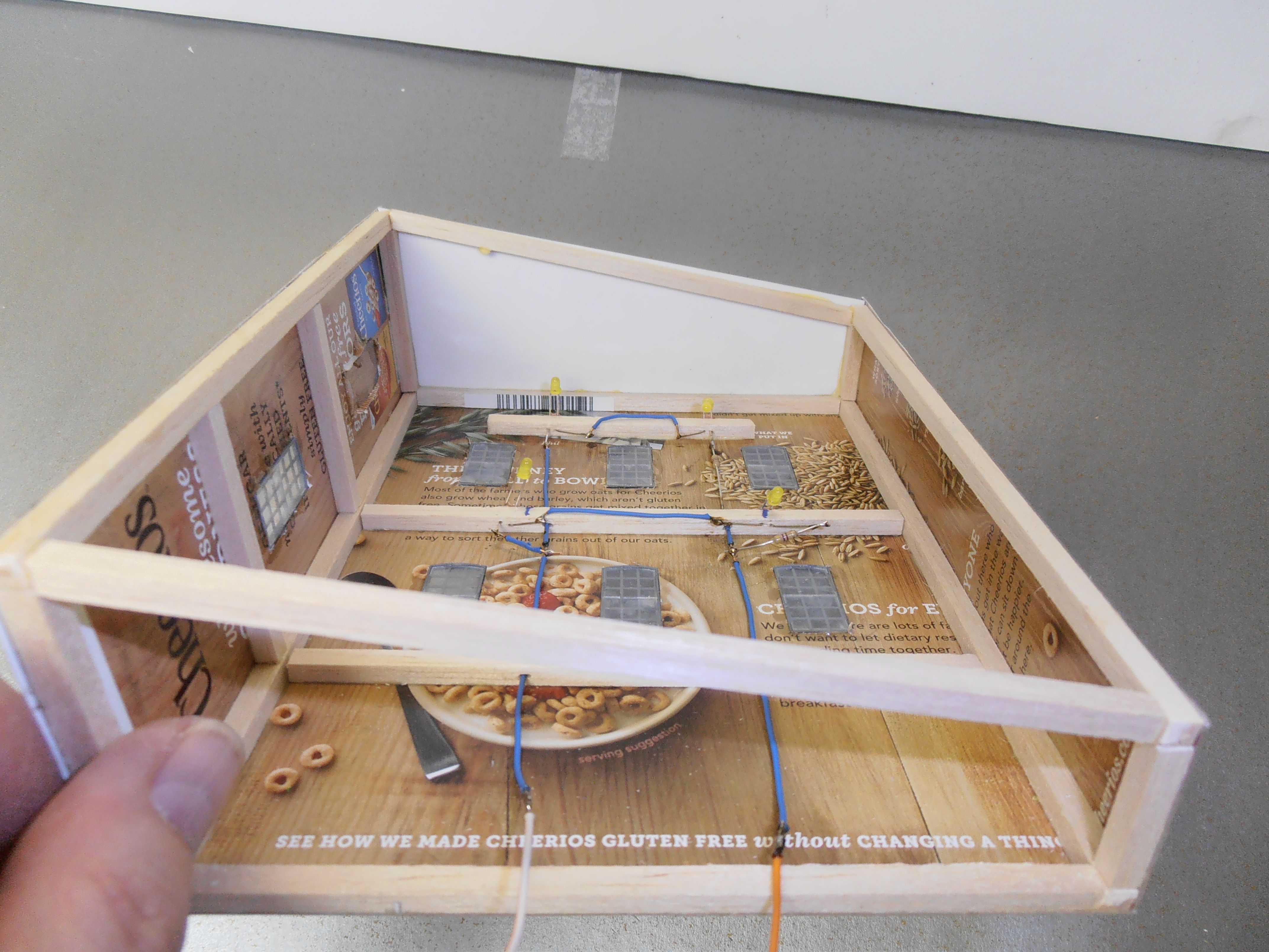
Photo 14 – LED lighting strips and wiring added
The roof can be fabricated at this time. I try to keep roof structure simple with minimal detail to the actual material used for the surface. Most of my backdrop buildings are very narrow in size so individually applied tarpaper covering and such would not be visible. It would also accentuate the actual narrowness of the building. I usually paint a piece of cardboard black that has been cut to the size needed for the roof. Next I add signs, chimneys, water tanks, skylights, vents, smokestacks, mechanical systems, and access doors to the roof exterior. (See Photo 13.) Don’t be afraid to have only half of a roof structure applied to a roof. One example of this is where I attached only half of a water tank to the roof. This type of ruse works well for tanks and cylindrical chimneys. When all the details are added I glue the roof to the building frame structure.
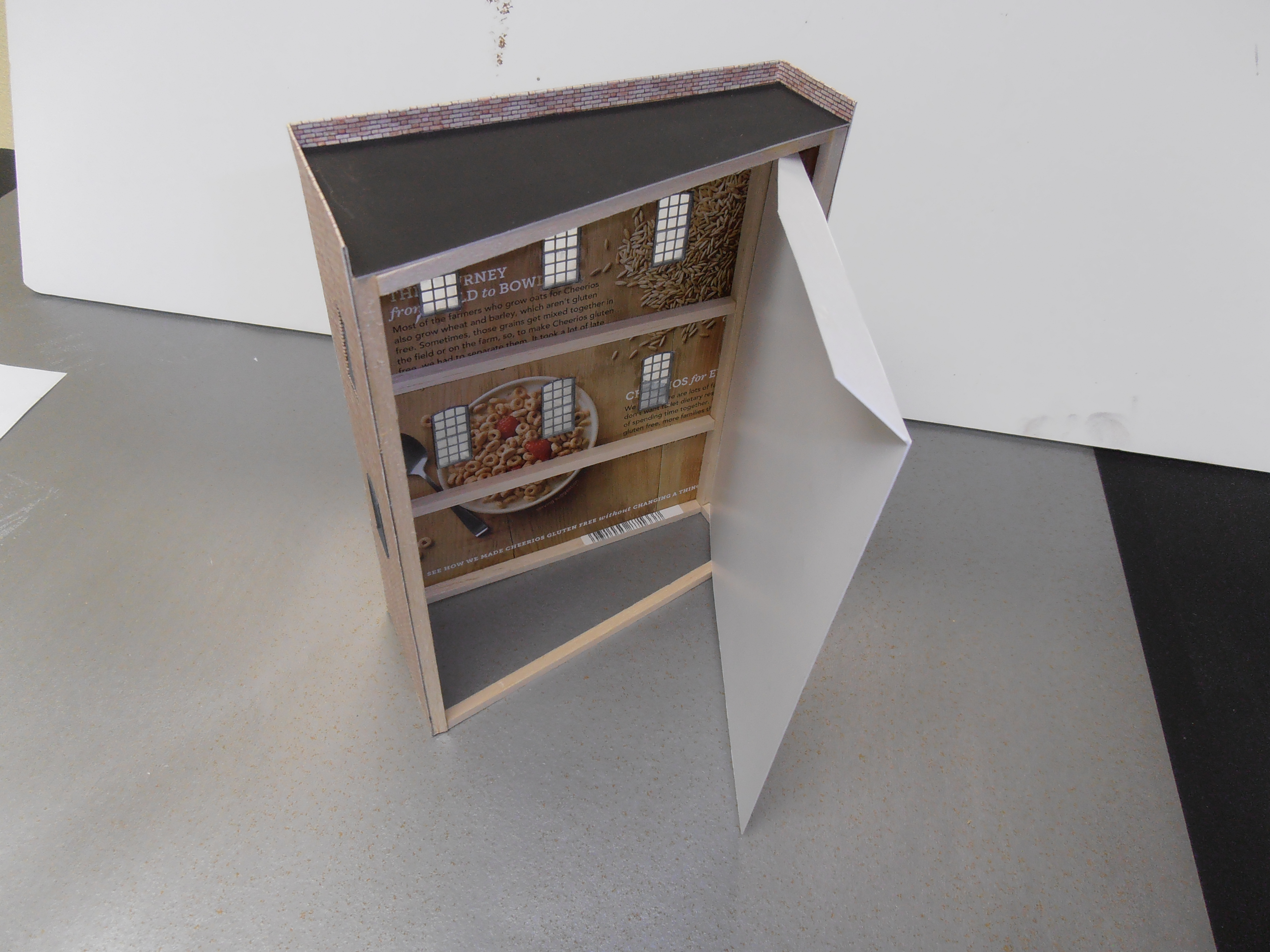
Photo 15 – Lighting reflector added
It is always nice to add building lighting and other interior details even to background buildings. This enhances the detail and adds interest to the structure. If a structure has a main freight door (or doors) I try to add a short platform on the inside of the building. The platform is usually less than 3/4 an inch wide and must not protrude past the side wall. Also, allow some space to place the building reflector. This allows the placement of crates, barrels, and especially workers to the inside of the building. Lighting is added by putting LEDs onto a strip of balsa or basswood. If the building is large I add several strips for lighting. These strips are glued directly to the building framing. I try to keep the wiring simple and since these structures are not contest models the wiring doesn’t need to be well hidden. (See Photo 14.) Next I add a lighting reflector to the back of the building. The lighting reflector is very simple to construct and is helpful in distributing the light from the LEDs throughout the building. My reflectors are composed of white cardboard that I obtain from work. (See Photo 15.) Some cereal boxes, especially those large ones from several warehouse stores sometimes have a white cardboard liner in them. They are an excellent source for the reflector. If all else fails you can make an inexpensive reflector out of the cardboard from a standard cereal box by spraying that material with cheap white spray paint. I usually size the reflector to fit snugly to the interior of the building. I butt the reflector directly against the interior platform and the reflector then becomes the back wall to the platform. The reflector is also glued to the building framing and becomes the back of the structure. (See Photo 16.)
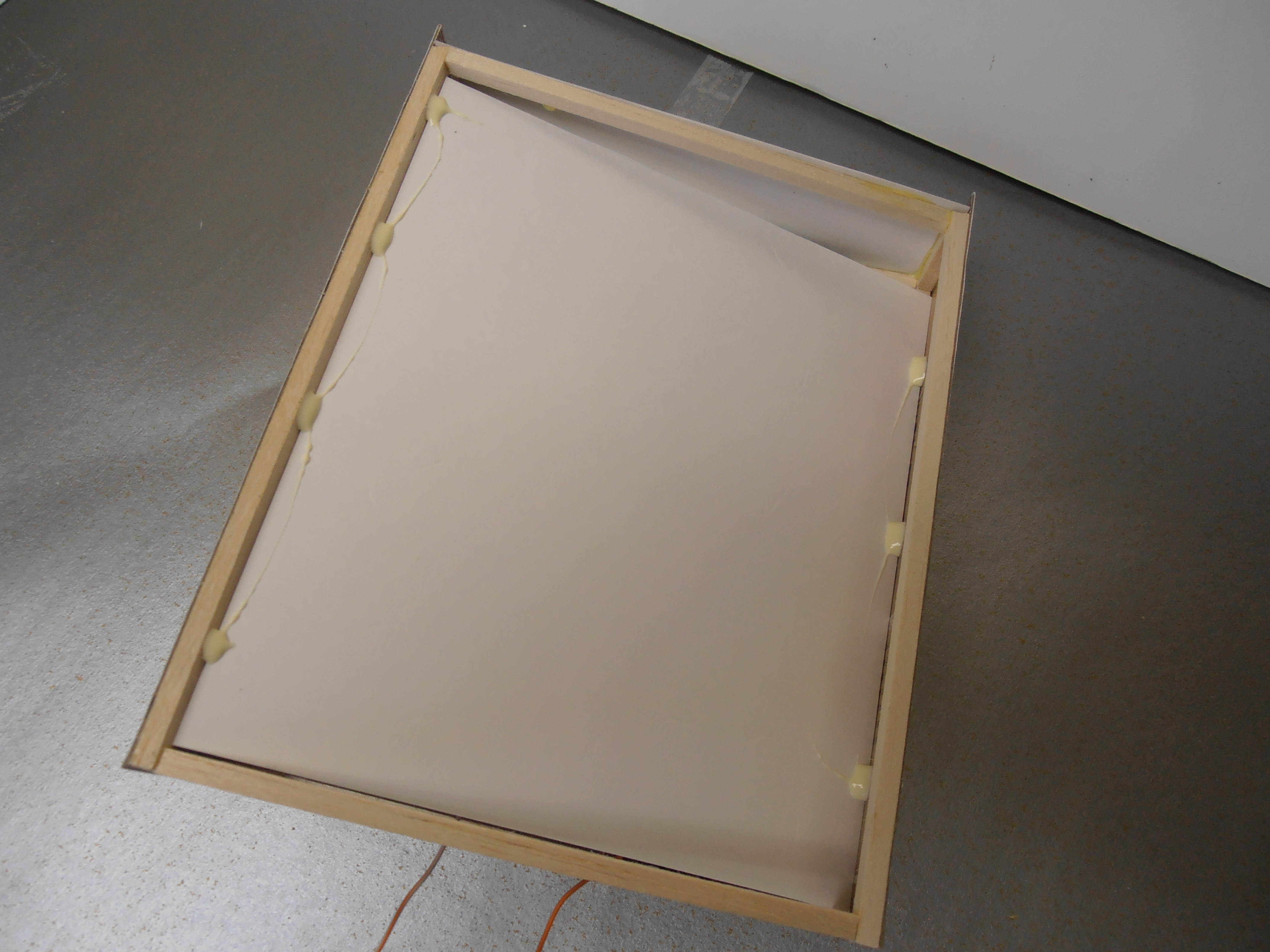
Photo 16 – Reflector becomes back of building
Details can now be added to the rest of the building. Signs or other exterior details can be attached. Stairs or loading dock truck bumpers can be added. Once everything is in place I then weather the structure with various chalks. The structure is then sprayed with a quick coat of clear matte paint (see photos 17 and 8). Again, take advantage of how and where buildings are placed on the layout. Make your life easy by omitting details that will not be seen by the observer. This structure did not need any foundation, loading dock, or loading dock doors in its location since just the upper two stories are visible. (See Photo 18.)
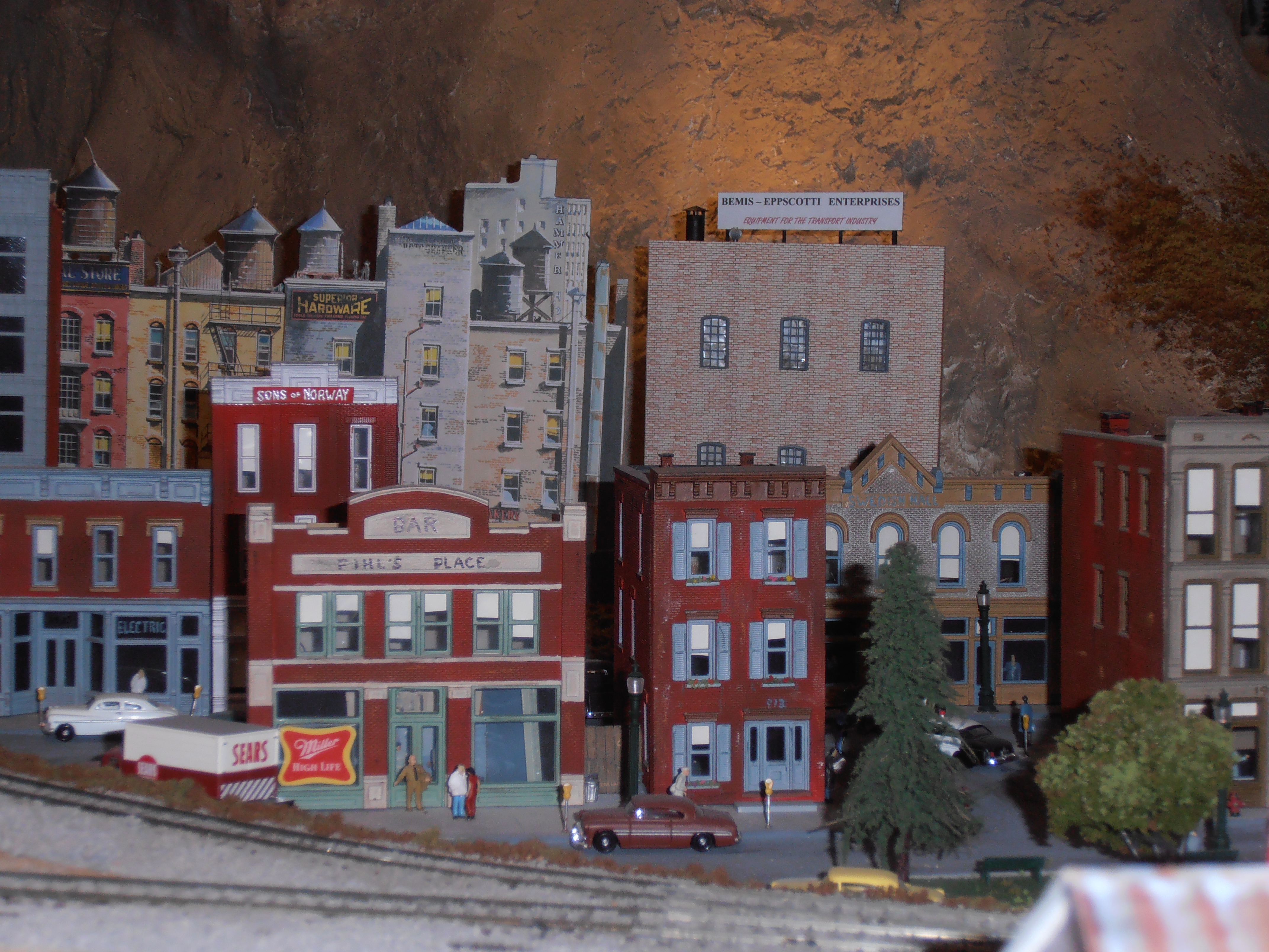
Photo 18 – Lower details omitted in background buildings
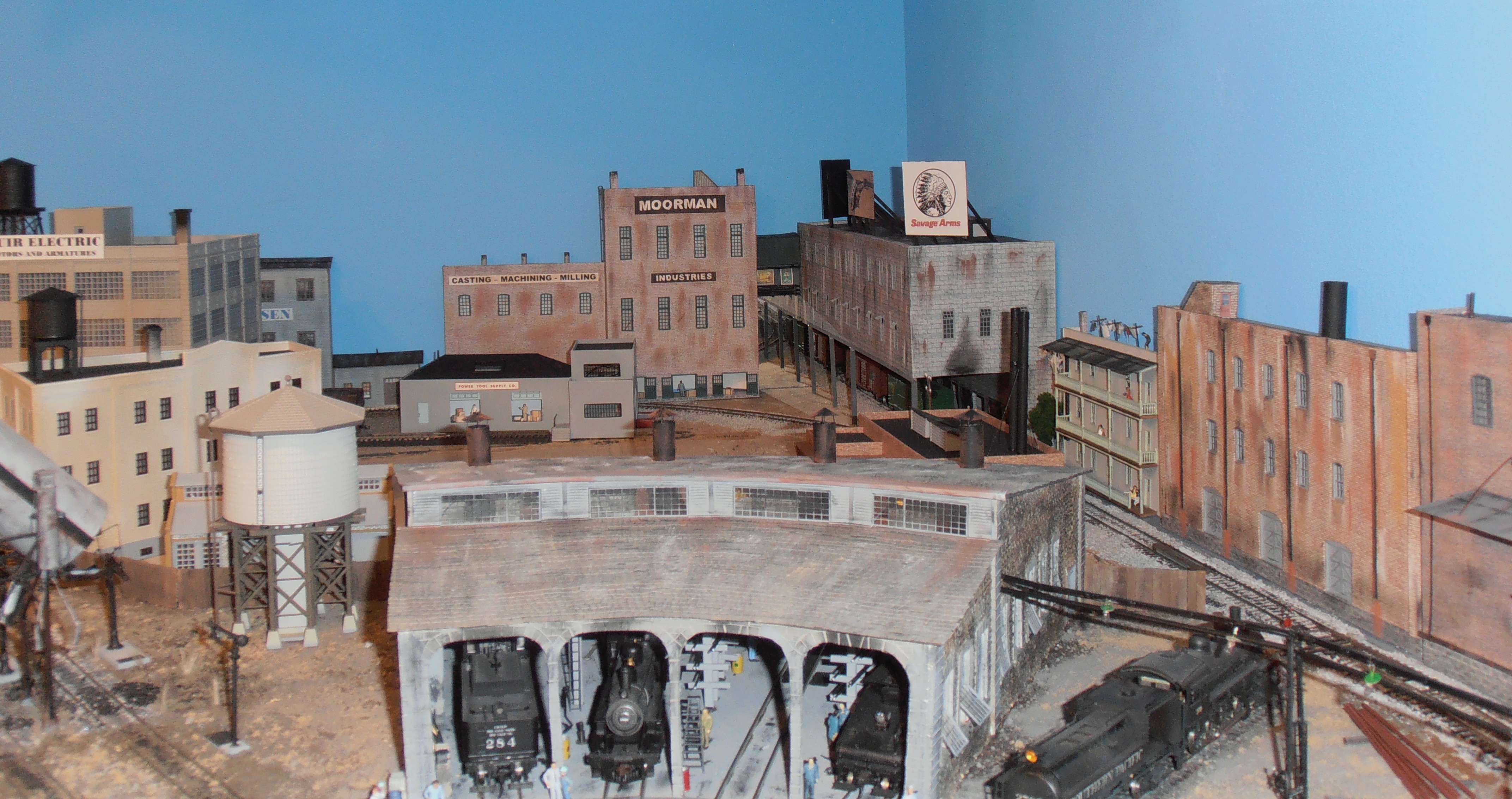
Photo 17 – Weathering applied
Nice work David
Very impressive work. Thanks for taking the time to share your techniques.
Very nice discussion of the construction process. I’m fond of using heavy styrene in leu of wood products as it is less apt to be affected by humidity. It appears that the same general techniques can still be applied. What is the source of your building material “Evan Design” software?
Paul, there’s a link in the article to the web site for Even Design software. Click on the link.
There are multiple versions of software on the site, so David may need to specify which one he uses. I’m guessing it’s “Model Builder”, although it could also be “Brickyard”.
Hi Paul,
It is Model Builder but it is an old copy of the software. I am not sure but I think they split the software up into two types now. My copy of the software allows me to print out many types of building materials as well as doors and windows. It also has the capability of printing out entire structures. I like it since I can vary the wall materials and their color.
Styrene is a good choice for a substrate but it also drives up the cost of the structure this hits hard with very large structures. My layout is in a climate controlled basement so I have no problems with humidity.
I buy my styrene in big sheets from Keltech in Tacoma. It’s only $2 to $3 a square foot depending on thickness.