
December 2013 Skagit Valley/Whidbey NMRA Clinic

Al Carter / Photos By Al Frasch

Clinic Chairperson Rich Blake welcomed all to our December clinic. He gave a brief rundown of upcoming model railroad related events in the Pacific Northwest, noting that the Fourth Division’s Pacific Science Center show will be held on MLK weekend, January 18-20 2014, and volunteers are always needed to help. Check the Grab Iron for more details.

Jack Tingstad reported that his annual open house over the Thanksgiving weekend was another resounding success – he estimates several hundred visitors came by to see his Cloud City And Western railroad and donated over 1000 pounds of food to the “Gifts From The Heart” food bank in Coupeville.

Al Carter gave a brief rundown on the upcoming PNR Convention to be held June 18-21 in Tacoma, WA and encouraged folks to attend. A great “warm up” for the NMRA National Convention to be held in Portland, OR in 2015.

Ted Becker was the featured clinician for the evening, with a program titled “Everything DCC” – which was a general overview of the DCC method of operating model railroads. Ted had asked earlier for people to send him questions that he could answer to the whole group, but the response was, er, underwhelming, so instead he made up his own questions.
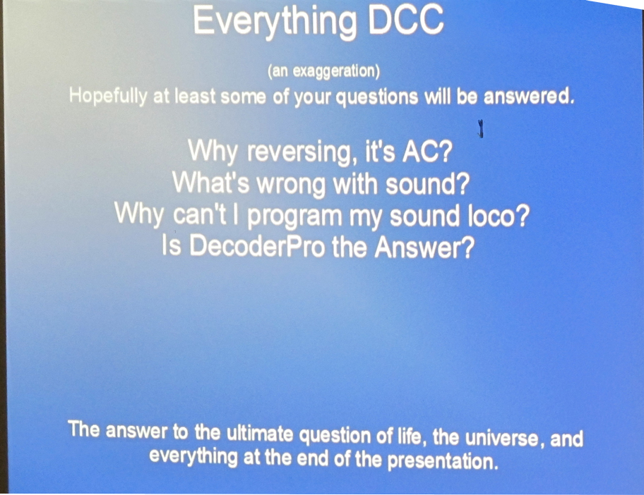
DCC Clinic Menue

DCC Clinic Menu

Among his “questions” was “What Is Wrong With Sound” (DCC sound decoders)? His answer, and this author is in agreement, is that sound decoders “out of the box” are generally too loud. When several sound equipped locos are running, they are filling the room with sound that becomes hard to distinguish. In Ted’s opinion, the decoders should be turned down so you hear the loco when it passes by you, but doesn’t overwhelm the room.

He also discussed the “keep alive” features that some DCC circuit boards are including these days (that keep the loco running when it encounters a brief dead spot, like a frog) – these keep alive features can create some programming issues.  ed mentioned some work-arounds.

Ted Becker wowing the crowd with his DCC expertise

Ted Becker wowing the crowd with his DCC expertise

Ted also discussed the various ways to program a locomotive, and mentioned the new BLI Address Changer (but he hasn’t had time to review it yet), and the Sprog unit (from England). Ted then went into a brief overview of Decoder Pro, and brought it up on the computer and screen so we could all see how easy it is to use. Ted had brought a small test system with him and actually used Decoder Pro to make some changes to the loco.

Ted suggests for help using Decoder Pro, you have several options – you can peruse the JMRI pages on the web, type questions into a web search engine, download the full manual, or join a Yahoo Group on JMRI and/or DCC systems. Plenty of options are available.

As there was a little time left over, Ted gave a brief ad-libbed overview of JMRI’S Operations software and how it can be utilized to make operations orders and switch lists. For more info on the JMRI Operations Software, see: http://jmri.sourceforge.net/help/en/html/apps/PanelPro/PanelPro.shtml

The January 2014 Clinic starts the new year off with a presentation “Be A Rock Star – Make and Take Rocks” by Jim Tartas on using the Joel Bragdon Geodesic Foam/Resin method of making rocks. I’ve seen Joel Bragdon give demonstrations on this method before and it is certainly an intriguing way to produce some great looking rocks without all the mess of using plaster or hydrocal. Don’t miss this clinic!

DCC Demystified

Dale G. Kraus

Decoding Sound Decoders

Model railroad sound has come a long, long way. When I was a young boy, I remember “sound” as being the wheezing air whistle of my Lionel set and the thunder of cast wheels on tubular track. I was always a little jealous of my best friend, who had a “Flyer” set that went chuff-chuff down the track, one chuff per wheel revolution. That was pretty much it until the introduction of PFM’s sound system in the mid ’60s and digitally-recorded sound boards in the following decade.

Then came the DCC revolution and the advancement of microprocessers and mini-EEPROMs. Hey! Presto! High quality, realistic sound that will fit into N scale locomotives. Just buy an appropriately sized sound decoder, drop it into your loco, set the address and you’re ready to go!

Well, almost.

Fresh from the package, all decoders, including sound ones, are set to “default” parameters. Some of these must be tweaked to get the most realistic sound performance out of your locomotive. In this article we will deal with diesel loco sound only — steam is a different animal. The CV’s (Configuration Variables) that should be altered to attain really convincing sound are:

  1. CV2 Starting voltage: For convincing sound, set this CV low enough that the loco does not start until the throttle has been advanced a few steps.
  2. CV3 Acceleration: Set to a value around 8-10.  This will allow the loco to increase speed gradually. If the loco still accelerates too fast increase the CV value. These two actions will allow the prime mover sound to “rev up” before the locomotive begins to move.
  3. CV5 Max speed: Most model locos are capable of running way too fast. As a starting point, set this CV to half of the maximum setting. This will slow down the loco and allow the throttle notching effect to perform more realistically
  4. CV6 Mid-range speed: Set to 50% of CV5.
  5. Sound Volume: The CV used for this varies with the decoder manufacturer. See your decoder manual (you did save the manual, right?). Turn this down dramatically. You should not be able to hear the loco a scale mile away! This has three advantages. First, the loud sound, while “Wow, gee whiz!” at first, can quickly become annoying. Second, if you are running more than one loco, the resulting cacophony detracts from the enjoyment of listening to the loco you are running. Third, high sound volume overdrives the small speakers we must use, distorting the resulting sound.

After you have performed the above five tasks, you can go back into the programming mode and tweak other sounds. With many sound decoders you can set the volumes of the bell, whistle, dynamic brakes, etc. See the CV table in you decoder manual. (Which you did not throw out, right?) Doing these five steps will make your loco sound as good as it looks.

DCC Demystified

Dale G. Kraus, MMR

Reverse Loops, Turntables, and Wyes … OH, MY!

(Apologies to Dorothy, Scarecrow, Tin Man, and Cowardly Lion.)

These three track alignments have been the bugaboos of model railroading since the invention of 2-rail DC wiring. Letting locomotives run through them smoothly and without shorting or stopping has required the use of toggle switches, relays linked to the position of switches and, for turntables, careful positioning of split pit rail pickup or similar installation on the central pivot shaft. While certainly a “do-able” method, the results were often fussy and required a lot of additional wiring.

Now we have it easy. Several manufacturers, Lenz, MRC, and Digitrax come to mind, have come out with a little magic box called the “Auto Reverser” which does the job without operator intervention.  How does it work?  Well…inside each device is a very tiny witch doctor with a machete and a large supply of minuscule chickens. When he senses the onset of an out-of-phase “short,” he quickly sacrifices one chicken and the problem goes away. (You’re buying this, right?) OK, OK! Actually there is a bunch of sensing circuitry and a fast-acting relay, but the first explanation is more fun. Each of these devices has a pair of “input” and a pair of “output” wires or screw terminals. The input is attached to the track buss and the output is attached to the “reversing section” or, through sliders, to the turntable rails.

The neat thing is, so long as the input and output wires are not attached “backwards,” i.e., hooking the input to the reversing section and the output to the buss, it does not matter which wire goes to which buss wire or rail.  The first loco to enter the section will properly align the reverser. If you do wire it wrong?  Not to worry; it just won’t work. The loco will just stop dead. If that happens, disconnect it and hook it up t’other way.

Now, keep in mind that this really is technology, not magic. The reversing section, be it loop, wye leg, or turntable track, must be completely insulated. Gaps must be placed in both rails at each end of the section and the turntable rails must not touch any of the approach track rails.  If there are switches in the reversing section, be sure that there are no “sneak circuits” through the switch. If there are, cut gaps beyond the frog in both rails of the diverging route. This will eliminate the “sneaker.” Be sure to feed the reversing section only through the reverser output.

One final thing: The reversing sections must be longer that the longest loco lash-up. For most of us this is no problem. If you are in N scale and insist on running mid-train and rear helpers, your reversing section needs to be short enough that the lead set and the first helper aren’t leaving and entering the section simultaneously. This will cause the witch doctor to have a schizophrenic episode and possible cut off his own head instead of the chicken’s. Smoke may mysteriously issue from the auto-reverser … NOT a good sign!

And please, DO READ THE INSTRUCTIONS!

DCC DEMYSTIFIED – 4

Dale Kraus

Speed Matching

Before getting into consisting, one more step needs to be taken. To have a smoothly running consist, all of your locos should run at (about) the same speed for a given speed step. Exact matching may be theoretically possible, but is far too fussy for practical implementation. What we really need is for the locos to start together and run realistically without excessive “bucking.” Unless they all run at about the same speed the faster locos will drag or shove the slower ones, decreasing the tractive effort and causing the faster locos decoders to run hot. This is not a good idea. 

To accomplish speed matching we need to use only three CV’s: CV2 (starting speed), CV5 (top speed), and CV6 (mid range speed). Assuming you have already slowed down your locos (DCC Demystified-3), follow the steps below for a “good enough” solution. 

First, select the loco that starts at the lowest speed step (usually step 2). This will be used as a standard for comparing the others. Place this loco on a three-foot long (minimum) test track. This can be on your layout, but I prefer a separate track. Take another loco and temporarily give it the same address as the “standard.”  Place the second loco on the test track about six inches from the standard, and start the locos. Adjust CV2 on the second loco until they both start at the same speed setting. To avoid having to take the “standard” loco off the track, simply tip it up on the far rail and place a sheet of paper under the wheels on the near side. Do this step for all your locos. Just doing this step will cure 80% of the problems that occur during consisting if you have already used CV’s 5 and 6 to slow down your steel steeds. If you are going to operate your RR before finishing the speed matching be SURE to return all locos to their primary addresses!! 

That’s enough for one night … go take a break. 

The next time you get ambitious, take the “standard” loco and one of the others and place them on your main line, about a foot apart. (If necessary, change the address of the second loco again.) Start ‘em up and go quickly to main line speed. Note if the second loco lags behind or catches up. Use the paper under the wheels trick to isolate the standard loco and, using Program on the Main, adjust CV5 on the other up or down. Check the two together again and change CV5 as needed. Repeat this drill with the other locos. Note here that they will NEVER run exactly at the same speed. Just get it close, as minor differences will not matter. Now, set CV6 to the mid-point between CVs 2 and 5. That will do it. 

Before you quit, remember to reset the addresses of all your locos.