A Narrower View – Track

Syd Schofield

Editors note: This is the second article of a new series on narrow gauge by Syd Schofield. The previous article is available by clicking here, or by filtering with the category “Narrow Gauge”. Syd welcomes discussions and feedback, which can be made by clicking on the comment link at the bottom of the post.

Narrow gauge railroad track isn’t much different than the “standard” four feet eight and one half inch gauge track on a lesser, “junior varsity” short line or a somewhat neglected spur. The main consideration is the weight of the heaviest wheel set to be supported. This results in a balance of rail strength and tie (or sleeper if you’re not from around here) spacing. So a K-37 would require heavier rail and closer ties, maybe even with tie plates to further spreads the weight over a larger foot print (bearing area) on the tie than needed by an 0-4-0.

In the early days (the Civil War and on) the materials involved were wrought iron with high strength alloy steel used later on. The rail deteriorates in elastic fatigue as a beam loaded between the ties as well as surface region fatigue due to the dual flexing (also elastic) of the contact area of the wheels, wheel on rail, with the rail top. Large rail grinding machines are used today to make an “insurance cut” of the affected rail top region. As rail was replaced due to fatigue and insufficient capacity, rails were often upgraded in size and material and the locally available, minimally prepared ties were upgraded with ties milled for tie plates and spike pilot holes off-site. Notably, spikes are made with a chisel point across the grain of the tie so as to break the fibers but remain supportive in the lengthwise direction as opposed to splitting the fibers opening an unsupported gap in the lengthwise direction.

What all this leads to is a hand driven single spike on each side of the rail in every tie for the earlier years / low budget / low capacity remote business or the store-bought closely spaced ties with tie plates and four spikes per plate for more modern or high capacity / well-financed business. With a little preparation of the Peco / Micro-Engineering / Shinohara nickel silver flex track and turnouts, to name a few, with an X-Acto knife and Dremel tool plus coloring and ballasting practices, the tie can look a little neglected and more representative of the frugal / back woods / mine supply / agricultural on a short life plan railroad. The actual time spent between the two methods is reportedly similar when appropriate skills and experience levels are achieved.

In addition to the Washington common carrier narrow gauge railroads previously mentioned we include the Alaska portion of the Pacific Northwest Region Forth Division: Golovin Bay Railroad, Seward Peninsula Railroad, Tanana Valley Railroad, and the still active and very popular White Pass and Yukon Railroad. And, as in Washington, there were numerous privately owned company railroads for support of logging, mining and other enterprises.

Picture Captions

Often a well-worded descriptive caption can turn a simple “record shot” photograph into a dynamic, interesting picture. In a still picture movement, effort, and sense of direction can be implied, creating an impression of time and purpose.

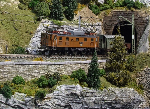
As an example, the attached picture is a rather bland shot of an electric locomotive emerging from a tunnel. With the caption, however, it becomes a much more captivating record of a train struggling to overcome a mountain grade.

SDEV in southeastern Schwabia

With the cooling blowers for its twin 26-pole motors screaming and the ammeters in the red, SDEV electric E68 046 is using all of the available 1250Kw to drag a freight up the 2.7% grade on the western approach to Triberg in southeastern Schwabia. There it will pause to cool the hot traction motors before making the final winding assault on “Das Teufelberg.” (The Devil’s Hill.) Click on photo for full picture.

A Narrower View – HOn3, Sn3, On3, On30, Fn3 (and more)

Syd Schofield

Editors note: Please welcome Syd Schofield, who will be writing posts in the Grab Iron blog on narrow gauge topics. He welcomes discussions and feedback, which can be made by clicking on the comment link at the bottom of each post.

Model trains, usually smaller than the real life things, generally fit our interests, space, time and budgets. The generally accepted, for various physical, business and political reasons, “standard” gauge (acceptance occurring from the Reconstruction period to well into the 20th century) for most US and Canadian common carriers was four feet 8 and ½ inches between wrought iron and steel rails. Smaller gauges of three feet and two feet also survived among the many other industrial, light transit and amusement purposes as did larger distances for specialized industrial purposes, however common sizes provided for economies of scale in production, operations and exchanges between railroads.

The HOn3 model size designates the “HO” (roughly the half “O” scale) of 1 to 87 parts, the “n” for narrower distance between rails than the standard gauge and the “3” is the actual full size distance in feet (a “30” or similar means 30 inches, versus feet). The general purposes of the full size railroad in this gauge was for smaller, less expensive equipment as well as the lower cost and more agile route preparation. These features made the three foot gauge attractive to any or all of rough terrain, lower capacity, lower capitol investment and short term business situations.

Washington State had at least three three foot gauge common carriers as well as many privately owned and operated by logging and mining interests. There were many three foot railroads and some even had dual gauge operations throughout the Western US, Alaska and other parts of Canada. Some were absorbed by larger standard gauge railroads while others succumbed to the truck, bus and automobile business successes or became historical amusements.

It is this period, simultaneous to the acceptance of the “standard gauge,” that many modelers choose to reproduce from “real” railroads based on historical situation or the merely technically correct for the chosen period creation of what might have been – in HOn3 (or other modeling narrow gauge scales). We would like to explore the activities of modelers in the PNR 4th Division, or anyone else with constructive intent pertinent to the three foot gauge railroads in brief and regular Grab Iron expositions. That is heavy on the “we” as pertains to anyone who would like to offer appropriate comments.

Miniatur Wunderland in Hamburg, Germany

Al Lowe

Last year, I was lucky to spend a day at Miniatur Wunderland, one of the world’s great model railroads in Hamburg, Germany. This for-profit operation, which appears to be quite successful, was filled with people at €12 each (about $15). Unfortunate, I learned after I arrived that I could have taken a “backstage” tour. Remember that for when you visit!

I edited my hours of footage down to less than 20 minutes to make this brief video. (Be sure to click the “full screen” button in the lower-right corner to watch in high-definition.)

Showing Your Model Railroad to Visitors

Dale Kraus

The layout open house season is approaching. I truly hope that those of you who have never had your pike open for visitors will consider doing so, as it is always enjoyable to see what someone else is doing in this most diverse of hobbies. With that in mind, here are a few tips for the first-timer, in no particular order, which the “old veterans” can follow too. They are all taken from my experiences as both a visitor and a host.

  1. Clean the track! Then clean it again. This avoids having to make excuses for the dirt.
  2. Select your best running locos, and use only the best 2 or 3 of those. Make sure the wheels are cleaned and the engine is lubricated.
  3. Run only your best, derailment-free cars. Clean the wheels of these cars. If there are any binds or misaligned couplers, park that car in the yard.
  4. Make up the trains you will run from these selected locos and cars.  Run each train completely around the pike 3 or 4 times. If anything derails, remove it.
  5. If you have any troublesome sidings or spurs avoid using them. If you cannot avoid their use FIX IT.
  6. Clean up the layout. Remove any distractions like pliers, screwdrivers and bright boys.
  7. If you have any bare spots simply cover then with dirt, grass and small bushes. If you have unfinished sections, that’s OK.
  8. Clean up the layout room and hide any construction materials.
  9. Make sure all locos and rolling stock on the layout are completely on the track. (Looks better that way.)

It’s always good to get a second set of eyes. Invite a buddy over and have him or her take a look. It’s amazing what might be found. I once left a water tower smack dab in the middle of a turntable pit. Interesting, but not very prototypical.

If you are going to have a buddy help you run the railroad, get together a day or two beforehand and run the trains you have selected. Agree on where the trains will meet. In this era of DCC it’s really easy to have cornfield meets. These are interesting and prototypical… but embarrassing. Back in the Seattle NMRA national, a friend and I were running trains and yakking with the visitors when one of the guests remarked, “I don’t think you really planned that.”  There on the grade, which neither of us could see well, were two steam locos, nose to nose and grinding away.

Remember: You’re among friends. If a gremlin pops up, we’ll understand.

DCC Basics

Dale Kraus

Thanks to Roger Heid and Ulrich Albrecht for this informative explanation.

In the old days, before the introduction of Personal Computers, electric model railroads were operated in the conventional mode. In the early 1980s, personal computers started to see increasing presence in common households. Subsequently, DCC was introduced to the world of model railroading.

DCC stands for Digital Command Control. The word digital implies the use or presence of a computer or a similar device. However, this did not result in the departure of conventional systems. They are still available. Be also advised that, for the purpose of this article, it does not matter whether you use a DC 2-rail or AC 3-rail system, although wiring the motors will be slightly different.

Now let us focus on the behavior of a conventional system. Chances are, when you were a kid, you received a starter kit for Christmas. Santa was kind, that year. Let us assume the locomotive that came with the kit had headlights, possibly even tail lights. You noticed that the brightness of these lights increased as you turned up the speed control of your power pack. They went out completely when you stopped the train. This probably annoyed you. In the real world, these lights are of constant brightness, no matter what.

In the world of analog model railroading, the power pack/speed control applies an increasing voltage to the track as you turn up the speed control. This explains why the lights behave the way they do. Not much you can do about this very easily.

This is not the end of the story. The following Christmas, Santa delivered another locomotive, because you had put in on your wish list. You were exhilarated. But then you noticed that, when both locomotives were on the track, they both ran simultaneously. That is not what you wanted.

In the meantime, a siding was added to your layout. Your plan was to park one loco on the siding while the other one was running around the track. Good luck with that. You wound up lifting the locomotive of the parked train off the track in order to allow the other train to run around the track. This was not a very desirable situation. You quickly figured out that an additional independent oval of tracks would solve the problem. By wiring an additional connection to your new track, you could now run both trains simultaneously, without collision. But you still could not stop one train while the other one was running. You quickly figured out you needed an additional power pack. Oh, Lord!

For the next Christmas, Santa brought the second power pack. You were in Seventh Heaven. You had separate control over your trains. Great! But now you wanted to be able to have the trains switch from one track to the other. You installed a couple of turnouts, in conjunction with short piece of straight track to connect the two hitherto independent tracks. You quickly learned it did not work that way. It caused problems. So you were forced to abandon that idea, unless you were willing to separate your layout into separately powered sections and install a multitude of switches that allowed you to turn off sections of track and/or connect them to different power packs.

The acquisition of a third locomotive required more tracks and a third power pack, along with more complicated panel switches and wiring. You then ran out of space to put in a fourth track, and so on.

At a later point, you heard about DCC. So, what is this all about?

DCC changes everything. In analog operations, you apply different voltages to your sections of track, and all locos on an individual section behave in the same way. Effectively, you operate your track, not the locos on it. With DCC, you “talk” to each locomotive individually, so you operate your locos, not your track!

First off, the term power pack/speed control changes to the term Control Station, which is a small computer. However, you do not need to know anything about computers to run it. No files, no commands! You now can address (talk to) an individual locomotive, not unlike making a phone call. You can tell it what to do. You can command one to run. Then you tell a running loco to stop, a third one slow down etc. With most Digital Systems you can control at least four locos, independently. This can vary by make and model of the system.

In addition to this, you no longer need to have electrically separated tracks. You can have all tracks connected in one contiguous circuit. You only need one control station and one transformer, usually two separate items.

Another benefit of DCC is how the lights behave, including those installed in a passenger car and EOT devices. Once track power is applied, they are all lit at a constant brightness, regardless what the loco does. How sweet it is!

In order to make all this possible, each locomotive needs to be equipped with a “Decoder”. This device receives the digital commands sent by the Control Station. It interprets the signal and will tell the loco what it is required to do, a decision you make, being the operator. Each decoder has its own address, similar to a phone number. All digitally equipped locomotives come with factory set addresses. They can be changed by the user, if needed. You need to know that no two locos on the track must have the same address. That is a No-Go!

Finally, another important issue needs to be addressed, namely the difference of track power behavior. There is a big difference between conventional (analog) systems and DCC. As explained earlier, in a conventional environment, the track voltage is increased as the speed control is turned up higher. When the speed control is turned all the way down, and the locomotive stands still, the track voltage is zero, which is why the lights go out.

In the DCC world, this is not so. Once the track power is turned on, which the operator does by pushing a button on the control station, the track power will immediately be at full voltage. This voltage depends on track scale and system. It will be somewhere between 12-18 Volts. The locomotive decoder needs the full voltage in order to function. At this point, the locomotive does not run, because it was not told to do so by the decoder, hence you, the operator.

The difference between DC 2-rail and AC 3-rail does not come into the picture here. All DCC systems behave very similar. The track power applied is a form of AC, but not a sine wave. It consists of a square wave. It is also not a 60 cycle affair, such as the common household current outlet provides. It is usually in the vicinity of 10 kHz (10,000 cycles). Newer decoder models actually step this frequency up to 15 kHz, to improve the locomotive’s running characteristics.

Then comes the next step. The decoder will send this raw track power through a bridge rectifier circuit to produce a smooth DC voltage to facilitate the proper functioning of the electronics contained on the decoder. The decoder then uses the data and the rectified voltage to produce a pulsating DC for the motor.

DCC systems, especially the more recent models, can also control functions other than locomotive speed and sound. This is another chapter in the book, geared for advanced users. Don’t let this scare you; it’s really quite easy.

By all this, it is necessary to keep your tracks clean and in good operating condition. DCC will not fix operating deficiencies caused by dirty tracks, pickup shoes and faulty track connections, leave alone locomotives in poor condition. In fact, such faults can seriously hamper smooth running on a DCC system. Furthermore, be prepared to spend a little more money than you may expect, at first glance, but usually less than a multi-cab analog set-up.

If you are serious about realistic train operation, the added expense is well worth it.

“Pay Day,” a Santa Fe Switchman Training Film

Rich Blake

This is a great period piece with a fair amount of humor that only makes sense in the 1950s era. It uses the example of a family’s busted TV to teach railroad employees to properly handle cargo during rail car shipping.

But this film should also make model railroad operators think about how you handle your switching operations. Do you back the loco into the string and keep going without stopping to check the couplings? Do you bash into strings and then take off in the other direction without allowing time to connect brake hoses and check couplings? Do you speed over turnouts to get to the runarounds because there is a lot of free track? Do you think about where your brakemen are located or where they must be dropped off or picked up by the engine or caboose? How many times have you backed into a string so soft and easy that only the couplers move as they connect? Or, when you back into a string does everything move an inch? What is “an inch” in your scale?

I’ve seen many cases, including myself, where operators get in a hurry or don’t pay attention that result in rough car handling and/or derailments.

This film illustrates these bad habits in 1:1 scale and emphasizes that we all need to slow down and go easy on the equipment. You never know what precious cargo is in there!

If the video doesn’t appear below, click this link to watch it on YouTube: http://youtu.be/nlzTqPfHrAI


Editor’s Note: Watching this film made me realize just how much things have changed in the past 60 years:

  1. You had friends over when you got a new TV
  2. Your wife baked them a cake
  3. Your wife baked
  4. He saved his money before buying something
  5. It was “his” money
  6. Men stood in line to get paid
  7. They got something called a “check”
  8. Multiple people were going to watch a 21″ screen
  9. The wife and daughter shopped for groceries
  10. TVs arrived via railroad
  11. The shop delivered
  12. She grocery shopped in heels and a dress
  13. The daughter wore black shoes and white socks
  14. He wore a coat
  15. The deliveryman’s handcart has 3” wheels
  16. TVs were made inChicago
  17. TVs had tubes. And wires.
  18. TVs came in wood cabinets
  19. With doors
  20. TVs were shipped in boxcars
  21. There were no forklifts in freighthouses
  22. Switches were thrown by hand
  23. Switchstands had kerosene lanterns
  24. A “fellow’s wife thinks he does his job just right”
  25. Livestock traveled by rail
  26. Airplanes had propellers
  27. Radios were the size of backpacks
  28. Ice was used for cooling
  29. Companies made slow-moving movies like this for training

It makes you wonder how different things will be 60 years from now!

– Al Lowe