 Dale Kraus / Photo by Author
Messtettener Kreisbahn 76cm gauge 0-6-2T No. 25 simmers on the turntable lead at Zindelstein as diesel No. 19 arrives with a train of anthracite coal jimmies.
You are browsing archives for
Dale Kraus / Photo by AuthorMesstettener Kreisbahn 76cm gauge 0-6-2T No. 25 simmers on the turntable lead at Zindelstein as diesel No. 19 arrives with a train of anthracite coal jimmies.
The layout open house season is approaching. I truly hope that those of you who have never had your pike open for visitors will consider doing so, as it is always enjoyable to see what someone else is doing in this most diverse of hobbies. With that in mind, here are a few tips for the first-timer, in no particular order, which the “old veterans” can follow too. They are all taken from my experiences as both a visitor and a host.
It’s always good to get a second set of eyes. Invite a buddy over and have him or her take a look. It’s amazing what might be found. I once left a water tower smack dab in the middle of a turntable pit. Interesting, but not very prototypical.
If you are going to have a buddy help you run the railroad, get together a day or two beforehand and run the trains you have selected. Agree on where the trains will meet. In this era of DCC it’s really easy to have cornfield meets. These are interesting and prototypical… but embarrassing. Back in the Seattle NMRA national, a friend and I were running trains and yakking with the visitors when one of the guests remarked, “I don’t think you really planned that.” There on the grade, which neither of us could see well, were two steam locos, nose to nose and grinding away.
Remember: You’re among friends. If a gremlin pops up, we’ll understand.
Thanks to Roger Heid and Ulrich Albrecht for this informative explanation.
In the old days, before the introduction of Personal Computers, electric model railroads were operated in the conventional mode. In the early 1980s, personal computers started to see increasing presence in common households. Subsequently, DCC was introduced to the world of model railroading.
DCC stands for Digital Command Control. The word digital implies the use or presence of a computer or a similar device. However, this did not result in the departure of conventional systems. They are still available. Be also advised that, for the purpose of this article, it does not matter whether you use a DC 2-rail or AC 3-rail system, although wiring the motors will be slightly different.
Now let us focus on the behavior of a conventional system. Chances are, when you were a kid, you received a starter kit for Christmas. Santa was kind, that year. Let us assume the locomotive that came with the kit had headlights, possibly even tail lights. You noticed that the brightness of these lights increased as you turned up the speed control of your power pack. They went out completely when you stopped the train. This probably annoyed you. In the real world, these lights are of constant brightness, no matter what.
In the world of analog model railroading, the power pack/speed control applies an increasing voltage to the track as you turn up the speed control. This explains why the lights behave the way they do. Not much you can do about this very easily.
This is not the end of the story. The following Christmas, Santa delivered another locomotive, because you had put in on your wish list. You were exhilarated. But then you noticed that, when both locomotives were on the track, they both ran simultaneously. That is not what you wanted.
In the meantime, a siding was added to your layout. Your plan was to park one loco on the siding while the other one was running around the track. Good luck with that. You wound up lifting the locomotive of the parked train off the track in order to allow the other train to run around the track. This was not a very desirable situation. You quickly figured out that an additional independent oval of tracks would solve the problem. By wiring an additional connection to your new track, you could now run both trains simultaneously, without collision. But you still could not stop one train while the other one was running. You quickly figured out you needed an additional power pack. Oh, Lord!
For the next Christmas, Santa brought the second power pack. You were in Seventh Heaven. You had separate control over your trains. Great! But now you wanted to be able to have the trains switch from one track to the other. You installed a couple of turnouts, in conjunction with short piece of straight track to connect the two hitherto independent tracks. You quickly learned it did not work that way. It caused problems. So you were forced to abandon that idea, unless you were willing to separate your layout into separately powered sections and install a multitude of switches that allowed you to turn off sections of track and/or connect them to different power packs.
The acquisition of a third locomotive required more tracks and a third power pack, along with more complicated panel switches and wiring. You then ran out of space to put in a fourth track, and so on.
At a later point, you heard about DCC. So, what is this all about?
DCC changes everything. In analog operations, you apply different voltages to your sections of track, and all locos on an individual section behave in the same way. Effectively, you operate your track, not the locos on it. With DCC, you “talk” to each locomotive individually, so you operate your locos, not your track!
First off, the term power pack/speed control changes to the term Control Station, which is a small computer. However, you do not need to know anything about computers to run it. No files, no commands! You now can address (talk to) an individual locomotive, not unlike making a phone call. You can tell it what to do. You can command one to run. Then you tell a running loco to stop, a third one slow down etc. With most Digital Systems you can control at least four locos, independently. This can vary by make and model of the system.
In addition to this, you no longer need to have electrically separated tracks. You can have all tracks connected in one contiguous circuit. You only need one control station and one transformer, usually two separate items.
Another benefit of DCC is how the lights behave, including those installed in a passenger car and EOT devices. Once track power is applied, they are all lit at a constant brightness, regardless what the loco does. How sweet it is!
In order to make all this possible, each locomotive needs to be equipped with a “Decoder”. This device receives the digital commands sent by the Control Station. It interprets the signal and will tell the loco what it is required to do, a decision you make, being the operator. Each decoder has its own address, similar to a phone number. All digitally equipped locomotives come with factory set addresses. They can be changed by the user, if needed. You need to know that no two locos on the track must have the same address. That is a No-Go!
Finally, another important issue needs to be addressed, namely the difference of track power behavior. There is a big difference between conventional (analog) systems and DCC. As explained earlier, in a conventional environment, the track voltage is increased as the speed control is turned up higher. When the speed control is turned all the way down, and the locomotive stands still, the track voltage is zero, which is why the lights go out.
In the DCC world, this is not so. Once the track power is turned on, which the operator does by pushing a button on the control station, the track power will immediately be at full voltage. This voltage depends on track scale and system. It will be somewhere between 12-18 Volts. The locomotive decoder needs the full voltage in order to function. At this point, the locomotive does not run, because it was not told to do so by the decoder, hence you, the operator.
The difference between DC 2-rail and AC 3-rail does not come into the picture here. All DCC systems behave very similar. The track power applied is a form of AC, but not a sine wave. It consists of a square wave. It is also not a 60 cycle affair, such as the common household current outlet provides. It is usually in the vicinity of 10 kHz (10,000 cycles). Newer decoder models actually step this frequency up to 15 kHz, to improve the locomotive’s running characteristics.
Then comes the next step. The decoder will send this raw track power through a bridge rectifier circuit to produce a smooth DC voltage to facilitate the proper functioning of the electronics contained on the decoder. The decoder then uses the data and the rectified voltage to produce a pulsating DC for the motor.
DCC systems, especially the more recent models, can also control functions other than locomotive speed and sound. This is another chapter in the book, geared for advanced users. Don’t let this scare you; it’s really quite easy.
By all this, it is necessary to keep your tracks clean and in good operating condition. DCC will not fix operating deficiencies caused by dirty tracks, pickup shoes and faulty track connections, leave alone locomotives in poor condition. In fact, such faults can seriously hamper smooth running on a DCC system. Furthermore, be prepared to spend a little more money than you may expect, at first glance, but usually less than a multi-cab analog set-up.
If you are serious about realistic train operation, the added expense is well worth it.
The rapid cannon-fire beat of three cylinder steam thunders off the walls of Bad Oos as SDEV 2-10-2T 85006 accelerates through the industrial section of town, “perfuming” the tower and surrounding businesses with the smell of coal smoke, steam, and hot hydrostatic oil.
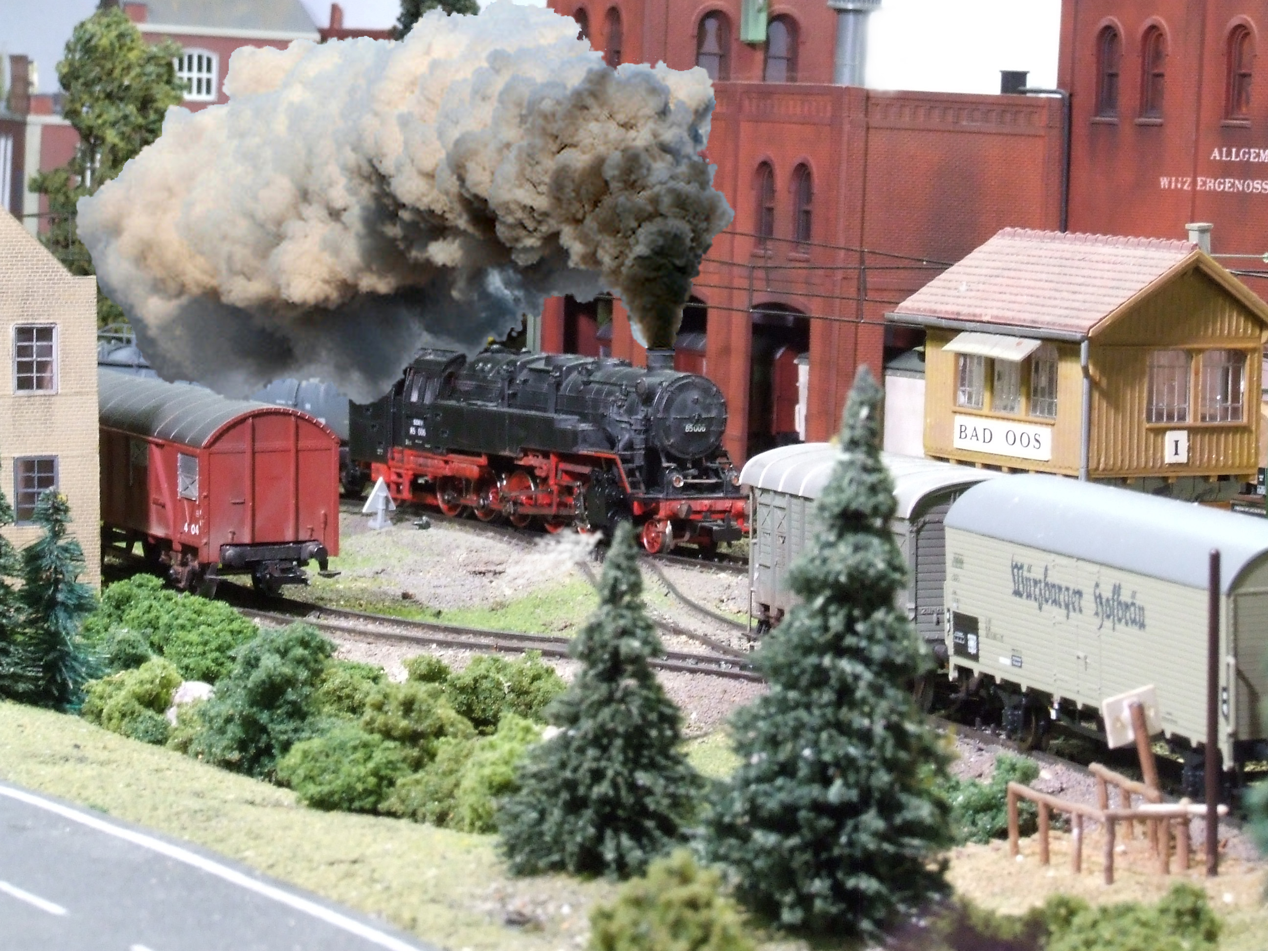
Photo: Larry’s Truck and Electric
Typical model railroader: Can’t decide on a prototype and has way too many locomotives!

Model railroad sound has come a long, long way. When I was a young boy, I remember “sound” as being the wheezing air whistle of my Lionel set and the thunder of cast wheels on tubular track. I was always a little jealous of my best friend, who had a “Flyer” set that went chuff-chuff down the track, one chuff per wheel revolution. That was pretty much it until the introduction of PFM’s sound system in the mid ’60s and digitally-recorded sound boards in the following decade.
Then came the DCC revolution and the advancement of microprocessers and mini-EEPROMs. Hey! Presto! High quality, realistic sound that will fit into N scale locomotives. Just buy an appropriately sized sound decoder, drop it into your loco, set the address and you’re ready to go!
Well, almost.
Fresh from the package, all decoders, including sound ones, are set to “default” parameters. Some of these must be tweaked to get the most realistic sound performance out of your locomotive. In this article we will deal with diesel loco sound only — steam is a different animal. The CV’s (Configuration Variables) that should be altered to attain really convincing sound are:
After you have performed the above five tasks, you can go back into the programming mode and tweak other sounds. With many sound decoders you can set the volumes of the bell, whistle, dynamic brakes, etc. See the CV table in you decoder manual. (Which you did not throw out, right?) Doing these five steps will make your loco sound as good as it looks.
Remember, guys & gals: For good operation of long passenger cars there can be NO kinks in the track!

(Emeryville, CA Amtrak Station)
(Apologies to Dorothy, Scarecrow, Tin Man, and Cowardly Lion.)
These three track alignments have been the bugaboos of model railroading since the invention of 2-rail DC wiring. Letting locomotives run through them smoothly and without shorting or stopping has required the use of toggle switches, relays linked to the position of switches and, for turntables, careful positioning of split pit rail pickup or similar installation on the central pivot shaft. While certainly a “do-able” method, the results were often fussy and required a lot of additional wiring.
Now we have it easy. Several manufacturers, Lenz, MRC, and Digitrax come to mind, have come out with a little magic box called the “Auto Reverser” which does the job without operator intervention. How does it work? Well…inside each device is a very tiny witch doctor with a machete and a large supply of minuscule chickens. When he senses the onset of an out-of-phase “short,” he quickly sacrifices one chicken and the problem goes away. (You’re buying this, right?) OK, OK! Actually there is a bunch of sensing circuitry and a fast-acting relay, but the first explanation is more fun. Each of these devices has a pair of “input” and a pair of “output” wires or screw terminals. The input is attached to the track buss and the output is attached to the “reversing section” or, through sliders, to the turntable rails.
The neat thing is, so long as the input and output wires are not attached “backwards,” i.e., hooking the input to the reversing section and the output to the buss, it does not matter which wire goes to which buss wire or rail. The first loco to enter the section will properly align the reverser. If you do wire it wrong? Not to worry; it just won’t work. The loco will just stop dead. If that happens, disconnect it and hook it up t’other way.
Now, keep in mind that this really is technology, not magic. The reversing section, be it loop, wye leg, or turntable track, must be completely insulated. Gaps must be placed in both rails at each end of the section and the turntable rails must not touch any of the approach track rails. If there are switches in the reversing section, be sure that there are no “sneak circuits” through the switch. If there are, cut gaps beyond the frog in both rails of the diverging route. This will eliminate the “sneaker.” Be sure to feed the reversing section only through the reverser output.
One final thing: The reversing sections must be longer that the longest loco lash-up. For most of us this is no problem. If you are in N scale and insist on running mid-train and rear helpers, your reversing section needs to be short enough that the lead set and the first helper aren’t leaving and entering the section simultaneously. This will cause the witch doctor to have a schizophrenic episode and possible cut off his own head instead of the chicken’s. Smoke may mysteriously issue from the auto-reverser … NOT a good sign!
And please, DO READ THE INSTRUCTIONS!
Here are a few tips from Sandy Webster concerning decoder selection and use.
I have used and liked the NCE DASR drop-in decoder on many of the old Atlas/Kato model Alco diesels (RS1, RS3, RSD5, RS11, RSD12, C424/5). I just discovered there is a drop-in decoder for the old Atlas/Roco model EMD diesels too, although it’s not labeled as such. It’s the NCE BACH-DSL decoder made to replace the really basic decoder in Bachmann diesel like my FT’s. I bought them figuring I might use them in my FT’s. I decided to use them in something else and have been looking at various candidates. I decided to try an Atlas/Roco SD24 since I had a couple with the shells off due to body kitbashing.
It’s a no-brainer, just as simple as the DASR. All I had to do was cut the wires from the trucks to the motor, unsolder the motor contacts from the actual motor tabs and replace them with wires, cut the old headlight bulb tabs off the top of the original plastic strip to make it level, run the 6 wires up through holes on the decoder and solder them to six pads. Add the supplied LED’s in the proper location and you are done. The LED’s may need wires to extend them to the proper place and pay attention to the polarity instructions. Don’t panic, it’s a picture! This works on the GP38, GP40, SD24 and SD35. One of the best things, the list price on the decoder: $19.95.
Sometimes ya gotta ignore the labels and use the decoder that fits.
Before getting into consisting, one more step needs to be taken. To have a smoothly running consist, all of your locos should run at (about) the same speed for a given speed step. Exact matching may be theoretically possible, but is far too fussy for practical implementation. What we really need is for the locos to start together and run realistically without excessive “bucking.” Unless they all run at about the same speed the faster locos will drag or shove the slower ones, decreasing the tractive effort and causing the faster locos decoders to run hot. This is not a good idea.
To accomplish speed matching we need to use only three CV’s: CV2 (starting speed), CV5 (top speed), and CV6 (mid range speed). Assuming you have already slowed down your locos (DCC Demystified-3), follow the steps below for a “good enough” solution.
First, select the loco that starts at the lowest speed step (usually step 2). This will be used as a standard for comparing the others. Place this loco on a three-foot long (minimum) test track. This can be on your layout, but I prefer a separate track. Take another loco and temporarily give it the same address as the “standard.” Place the second loco on the test track about six inches from the standard, and start the locos. Adjust CV2 on the second loco until they both start at the same speed setting. To avoid having to take the “standard” loco off the track, simply tip it up on the far rail and place a sheet of paper under the wheels on the near side. Do this step for all your locos. Just doing this step will cure 80% of the problems that occur during consisting if you have already used CV’s 5 and 6 to slow down your steel steeds. If you are going to operate your RR before finishing the speed matching be SURE to return all locos to their primary addresses!!
That’s enough for one night … go take a break.
The next time you get ambitious, take the “standard” loco and one of the others and place them on your main line, about a foot apart. (If necessary, change the address of the second loco again.) Start ‘em up and go quickly to main line speed. Note if the second loco lags behind or catches up. Use the paper under the wheels trick to isolate the standard loco and, using Program on the Main, adjust CV5 on the other up or down. Check the two together again and change CV5 as needed. Repeat this drill with the other locos. Note here that they will NEVER run exactly at the same speed. Just get it close, as minor differences will not matter. Now, set CV6 to the mid-point between CVs 2 and 5. That will do it.
Before you quit, remember to reset the addresses of all your locos.