Click here to read the July 2023 issue of The Flimsy Board from the Bremerton Northern Model Railroad club.
You are browsing archives for
Category: Articles
How to’s, presentations, and informational articles
Why I Appreciate Tinplate
By Ed Ives
My earliest memories of trains were as a very, very, small child being carried into a room and on the floor was an oval of shiny 0 gauge tin track with a colorful train running around on it. Wow, I was set for life but with a few branchlines.
As a six year old for Christmas 1948 I was introduced to 00 gauge, a Hornby Dublo goods (freight) set that when in use was done so with adult supervision and when out of use was stored in my parents closet. This way it survives to this day although much added to over the years in its glorious three rail, tin printing and not a piece of plastic in sight. Yes you read it correctly, three rail 00 or H0 track!
As a young adult I had a hankering for ‘model’ trains as opposed to those compromised ‘toy’ trains and started down the track (excuse the pun) of scale British outline model trains in two rail 00 gauge. It was there that I realized 00 is not quite a scale gauge. The superstructure of the 00 gauge trains are 4mm to the foot whereas the track is H0 16.5 mm gauge or 3.5 mm to the foot and not 18.9 mm gauge. I felt a need for more precise modelling and investigated EM gauge or 18 mm gauge track, as well as P4 and S4 that were emerging with precise 18.9 mm gauge track and components.
I soon settled on EM gauge and would now need to make my own track as no EM gauge track was commercially available. I had grand plans for a large layout in the garage and decided to start building some simple stock like an 0-6-0 tank engine with no external valve gear and three passenger coaches, all from kits. With the interest in precision I purchased a book by David Jenkinson of British LMS passenger coaches. I started with the construction of the locomotive, a cast while metal kit of an LMS 0-6-0 Jinty. Hum, the kit left a lot to be desired as the two halves of the mold were not quite registered correctly which resulted in the need for a lot of filing and filling to get the boiler circular etc. I also discovered that with the wheels at the wider EM gauge then fouled the running plates on the side of the boiler and more metal removal would be required.
OK, putting that aside for a while, I started work on the coaches. Nothing could be simpler, or so I thought, as the kits comprised three basic components; a one piece plastic body, a metal underframe and a metal roof. Added to this were white metal castings of the trucks and truss rodding. Nothing much more than shake the box and all is assembled, or so it would appear. The plastic bodies lacked the hand rails and door handles as indicated on the drawings in David’s book. These were made from piano wire and installed. Oh, I need high frequency interior lighting for the coaches, or so I again thought, this of course being prior to DCC. Effective lighting was made using 1/8″ thick perspex, a grain of wheat bulb and some aluminum kitchen foil as a reflector. An old black and white TV was collected as a source of components for the construction of the high frequency lighting generator until a friend enquired about a license for it? License, what license? It seems that the generator might broadcast a signal and a broadcasting license might be required. Well I put that aside for a while wondering if even applying for a license would be a good idea or not.
Still on a roll I set to work on the coach roofs. Hum, a problem here as the supplied roofs were a little too short, of the wrong curvature and otherwise of no use. I will have to make new ones but how? Drape forming plastic came to mind. A mold was constructed using sheet metal and plaster. Plastic sheets from the model store were carefully placed on the mold and gently heated in the kitchen oven. Oh disaster! The plastic instead of draping over the mold would shrink and curl up, a total failure. Obviously the plastic had a memory that could not be easily overcome. A backup plan materialized making the roofs from galvanized sheet heating duct and proved to be quite easy to do. Now to add cast white metal ventilators and rainstrips made from piano wire. These were soldered to the roofs and the assemblies placed on the coach bodies. Hum these are looking quite good. Now for the underframe and trucks. Stepboards needed to be added to the trucks and were made from wood. The castings of the trucks and the truss rods needed some fettling to clean them up. The underframes lacked a lot of the details such as battery boxes and generators etc. that would be slung below. All this stuff was made using scrap materials available on the worktable and added. The plastic buffing gear on the coaches were cut off and sprung metal buffing gear added. The wheelsets that came with the kits were regauged to EM standards. Finally a length of track was made and the coaches were placed thereon. I say finally as this had only taken me three years to produce to this stage and I hadn’t begun to paint the coaches yet.
I was unhappy with the glazing of the windows due to the overly thick plastic body sides. I read that one could make individual windows from glass microscope slides. A count of the number of windows to be treated gave me a sickening feeling in my stomach with something like 120 windows to be made of two different sizes. I agonized over the guards (conductor) duckets on the sides of the brake coaches. These in the kits were solid bumps on the molded coach bodies. In the 12″ to the foot coaches these were hollow with small windows facing forward and aft that the guard could look out of and verify the signal aspects and the precise location of the train along the track. No window openings were provided on the model and how should I make them; hollowing out the plastic?, or removing the plastic ducket and making new hollow ones to be added? I finally decided to leave it alone for another time, our model guard would have nothing to look out of. The nail in the coffin or very nearly so, came when I tried to paint the coaches with Floquil primer. I thought I had the darkroom come laundry adequately ventilated with a box fan in the open window and my improvised cardboard paint booth, but not so, and I was quite unwell for a few days following the painting attempt. I also noted that the Floquil vapors apart from attacking my lungs attacked the plastic coach bodies but not fatally so in either case.
Much as I was pleased with the results so far, life would not be long enough to achieve my aims of a large working train layout, especially so, since children started to be added to the family. For the next twenty years the trains were put away due to family constraints.
When I resumed with trains in my late 50’s I could appreciate the advantages of colorful, noisy, ready to run, 00 and 0 gauge tinplate from so many years ago. Those collections resumed for the Hornby Dublo or began for 0 gauge, three rail of course. The Hornby Dublo collection is now assembled as a large layout in the spare/train room and the 0 gauge runs with the Hi-Rail modular group.
Life is good.
Yours,
Ed Ives
Bremerton Northern April 2023 Flimsy
Click here to read the April 2023 issue of The Flimsy Board from the Bremerton Northern Model Railroad club.
Bremerton Northern January 2023 Flimsy
Click here to read the January 2023 issue of The Flimsy Board from the Bremerton Northern Model Railroad club.
Bremerton Northern December 2022 Flimsy
Click here to read the December 2022 issue of The Flimsy Board from the Bremerton Northern Model Railroad club.
Pseudo Block Signaling
By Ed Ives
Background
As a small boy at the end of WWII I was taken to see my great aunt who lived in the station masters house on a small country station. It was there that I was invited into the station signal box to see the levers and listen to the bell codes. The line was double tracked and at the end of each platform were the signals that governed the passage of the train. Every few miles down the line was another station with a signal box and signals. In those days the mechanical signals were all set at danger and pulled off for a passing train. Some years later the local signal boxes were replaced with power area boxes that controlled the passage of trains in a district. Later still came the color light signals and a change with block signaling where the normal aspect of a signal was green, changing to red when the block ahead is occupied, or amber if the block ahead is clear but the second block ahead is occupied. This was not fully realized by me at the time, as I would stand beside the green signal on a Sunday afternoon train watching for the train that rarely came.
Signaling on model train layouts
As a boy I always imagined a train layout with working signals and how to make that happen. It was obvious to me that running a couple of trains and manually operating the signals on any feasible layout would be highly unlikely verging on the impossible. The layout never came to be, but some years ago I joined the Hi-Rail modular group. Soon I started to think about signalling as my contribution to the layout. Color light signals seemed to be the obvious simplistic approach using a block signal logic. We already had operating accessories that were activated by a passing train but somehow we needed to simulate a section block. I quickly came to the conclusion that to make this happen would need yards and yards of wire, many connectors and a uniform approach to make this work in any layout arrangement. The idea was put aside, until recently.
I was rummaging through some Youtube videos and came across one labeled ‘Automated color light signals on a budget.’ The demonstration looked quite good, no computers and nothing to program, but did not mention the manufacturer of the equipment other than the items were available on Ebay. I followed up with a Google search and found a Chinese company ‘WeHonest’ that has an Ebay catalog featuring parts for multiple scale model railroads. Quite frankly I was not initially enthused about a company with such a name and less so when they advertised O gauge double aspect color light LED signals for the cost of a Starbucks coffee. With little to lose, I ordered a pair of signals. They arrived about ten days later and were made of gray painted brass and came with red and green LED lights already wired and all for $4 each. They looked very fine, so I went to the next level, or how to make them work. The company offers a manual switch to control the signals or a master board for automatic control. The master board is about the size of a pack of cigarettes and comes with an IR detector on a 12″ cord, all for $20. One also needs a power supply with various options such as off the train transformer. I chose the simplest option and that was to buy a small transformer that plugs directly into the master board for $13. I’m sure that one could buy these elsewhere for $5 but they do come with a convenient coaxial plug fit for purpose. The search for the alternate would not be worth my effort. So now I have all the components of a working signal for less than $40.
Time for a test track and a learning experience. The wires from the signal are very fine and are difficult to secure in the terminal strip on the master board. The IR detector was located in the track and is equipped with a plug to attach to the master board. Pretty darned simple and a test was made resulting in total failure. Oops, one of the signal wires came loose from the terminal strip and this became a recurring problem. OK a simple solution was to make the wire thicker as it attaches to the terminal strip. An improvement was achieved but still a failure in that the green light changed to a permanent red after about one second of turning on the power. I chewed on this for a while until a magic thought came to mind, how about reading the instructions?, 13 pages of them, although not having done this before. In fact in this case only two pages are of significance, 1) a large scale diagram of the master board and 2) the set up for the specific task, i.e., dual aspect signals. Here it is revealed that the master board is the heart of quite a few interesting controls involving train detection. What came to light was that the master board has a bank of eight very small switches that need to be selected in a specific sequence of on and off. I needed a magnifying glass to see this clearly, or that is my excuse. Once set per the directions everything worked fine. The next test was about durability and how long they will work.
Two modules were equipped with the signals and were ready for the Lynden show. The signals worked fine until the sun shone on the IR detectors and functioning stopped for the rest of the day. It was 88 degrees outside and bright sunshine. The next day all worked well until the sun came in through the windows in the roof of the building.
For Maple Valley there were no windows in the building roof and the signals worked without a hitch the whole weekend.
The signals work as follows:
- The normal setting is green.
- A train passing the signal and the IR detector turns off the green light and turns on the red light.
- The IR detector recognizes the end of the train and triggers a timer that when run down turns the red light off and the green light on. At the moment the timer is set for 10 seconds which is OK for most purposes.
Master board
The master board can control two, three, or four aspect signals and is the primary control for highway traffic lights, grade crossing signals and more. If so, it’s an ingenious piece of kit. I hope to check that out in the not too distant future.
Ed
Bremerton Northern November 2022 Flimsy
Click here to read the November 2022 issue of The Flimsy Board from the Bremerton Northern Model Railroad club.
Bremerton Northern October 2022 Flimsy
Click here to read the October 2022 issue of The Flimsy Board from the Bremerton Northern Model Railroad club.
Bremerton Northern September 2022 Flimsy
Click here to read the September 2022 issue of The Flimsy Board from the Bremerton Northern Model Railroad club.
David Yadock’s Dry Gulch & Western Update 11
Article & Photos By David Yadock
Dry Gulch & Western, Update 11
It has been a while since my last update. In this latest edition I’ll show you some of the new scenery that has been added to the Dry Gulch & Western layout. The alcove portion of the layout was targeted for scenery completion for the National Narrow-Gauge Convention. The convention will be held in Tacoma on September 1-4 of this year. My layout is one of many fine local layouts in the area that will be open for tours. If you haven’t already signed up for the convention, I really do recommend it. There will be lots of things to see and do. Here is the link for the convention www.seattlenngc.com , check it out today and sign up!
I decided to work on this portion of the layout to allow visitors a more complete view of my layout’s mountainous region and attempt to complete the town of Hayes River. The completed scenery in the alcove also tied together two large sections of the layout that already had scenery in place for a while. Naturally this is a progress report, some structures still need to be built, but most of the major scenery items are in place. I will continue to build structures up until the convention. Hopefully I’ll have all of them in place by September. Please don’t hold your breath on that one but I will give it my best shot!
To be a little different than previous updates I’ll show a photo progression of the scenery in this area. This will give you an idea of all the changes that have occurred over the years and how the scenery has evolved.
Photo 59 is a really old view of the layout looking down the aisle leading to the alcove. This photo shows the framework and track position. The photo also shows that the major bridges are being placed in position. Please note the large mirror in the room corner. Just a sprinkle of scenery and it is all done!
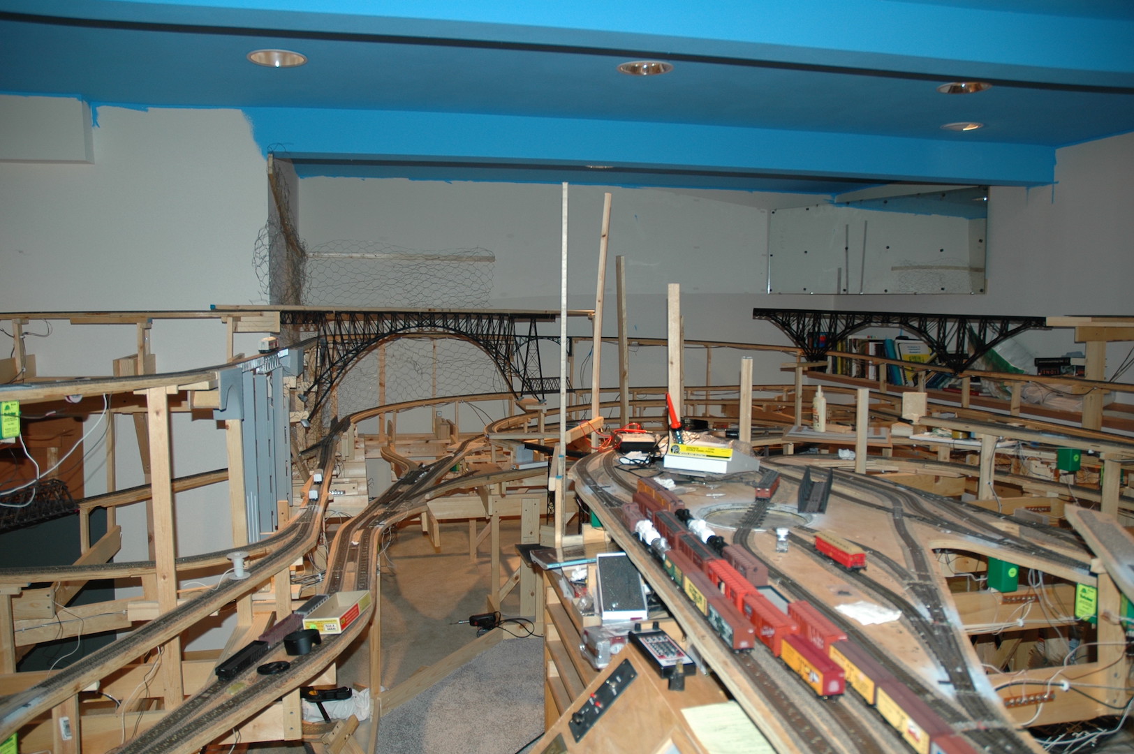
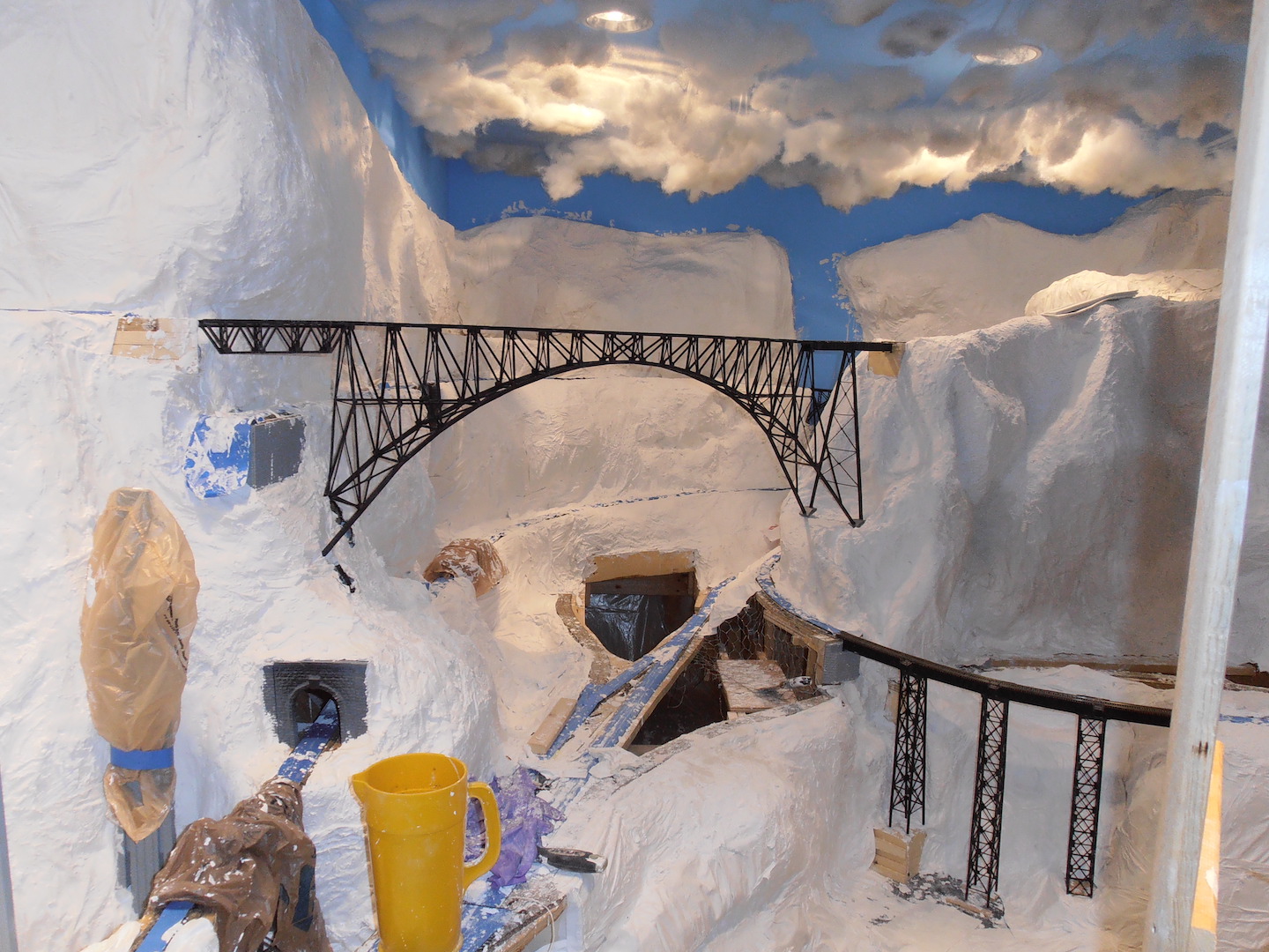
Photo 60 shows the same general area with the plaster applied. Application of Hydrocal plaster-soaked paper towels was messy but rewarding. It gave the general shape of the mountains and topography. It also reflected the overhead lighting quite well!
Photos 61 and 62 now shows some of the area with varying shades of paint applied to the plaster. This helped with the general appearance of the layout. This whole area was left dormant for quite a long time while I was concentrating my time applying scenery to other areas of the layout. The good thing about holding off with scenery application in this area allowed me to plan the types of terrain that will form the final scenery. Since I delayed scenery application I was able to re-adjust a critical access hatch. The hatch was condensed in size and shape. The retaining mechanism for the hatch was also changed to a simpler system. By changing the hatch, I gained some space to allow for another siding to be added. This increased operational capabilities in the small town of Hayes River.
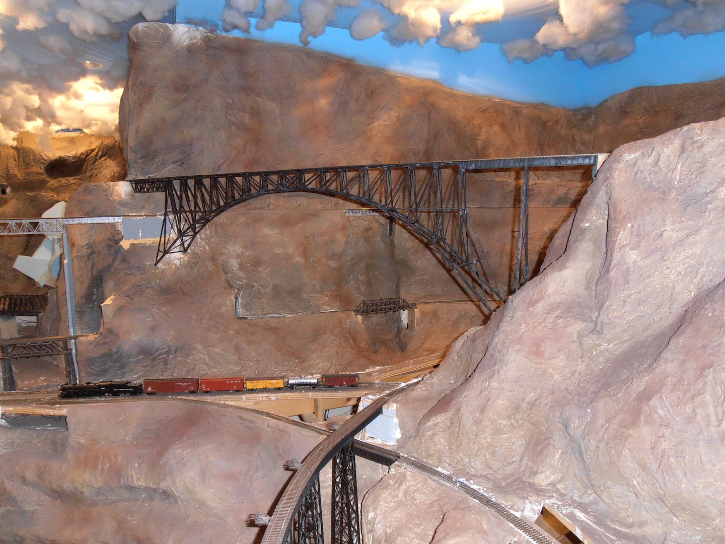
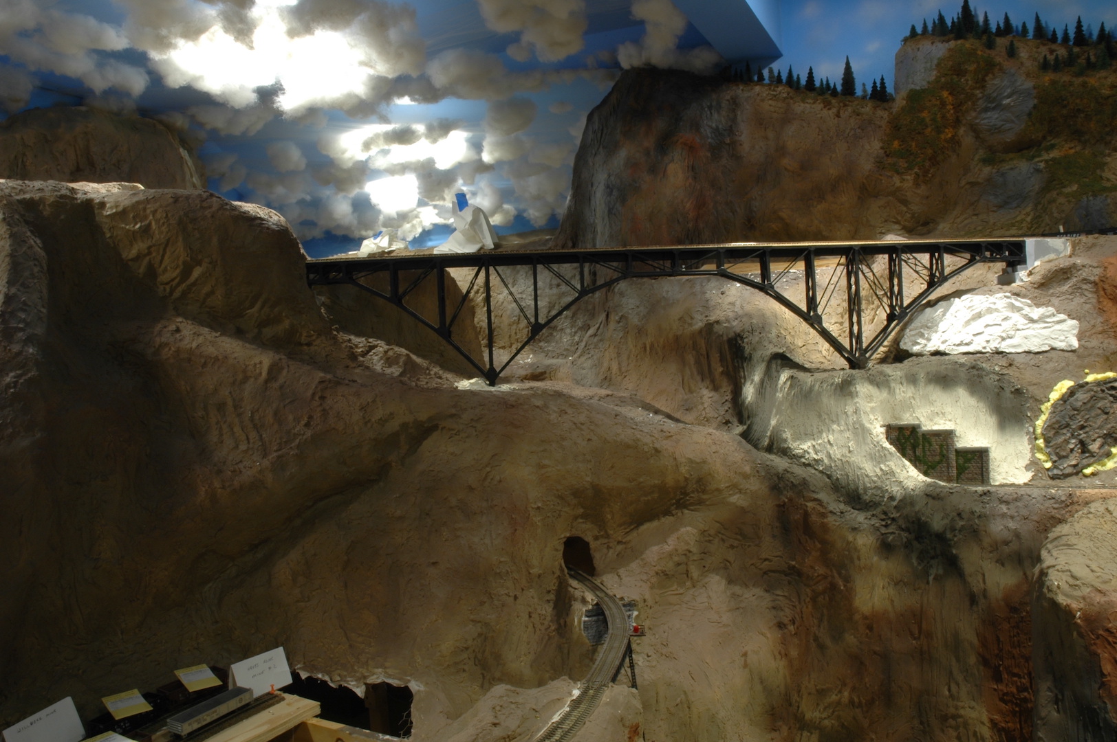
Photo 63 shows the latest version of scenery in this area. The track has been ballasted, ground cover has been applied, and various trees have been planted. Yes, structures still need to be built and installed. In the photo you can see that the town of Hayes River now has a station! It is the green structure partially hidden behind the rock outcropping.
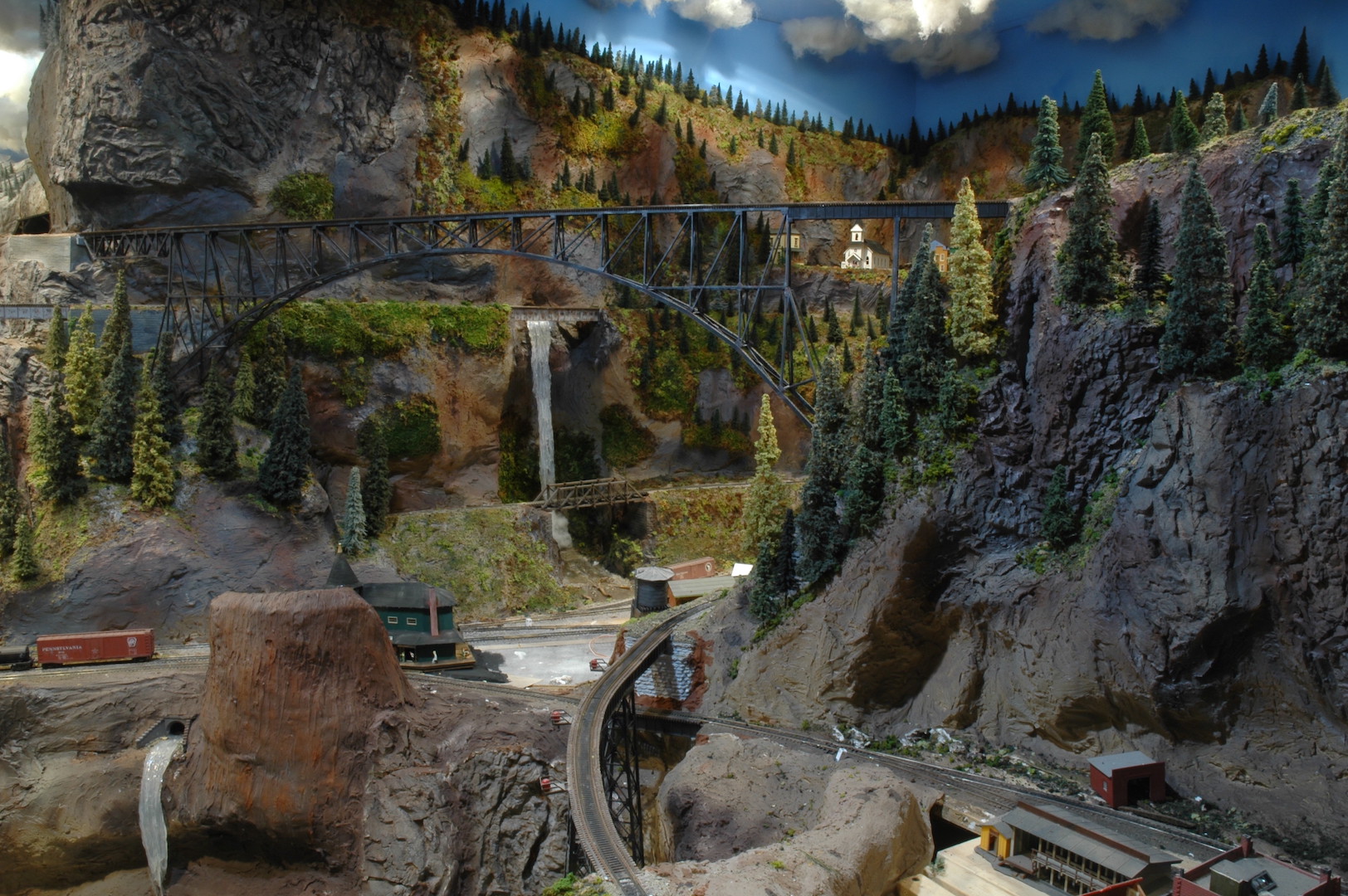
Photo 64 Is a great view of my version of the Canyon Diablo bridge. This bridge carries the mainline to the town of Alpine and beyond. As many of you know my layout is loosely based on the famous Gorre & Daphetid layout that John Allen built. On John’s layout the bridge was never completed. Due to the lack of a bridge, he never had a fully operational mainline. Early on I decided to construct all the bridges so that the mainline would be complete.
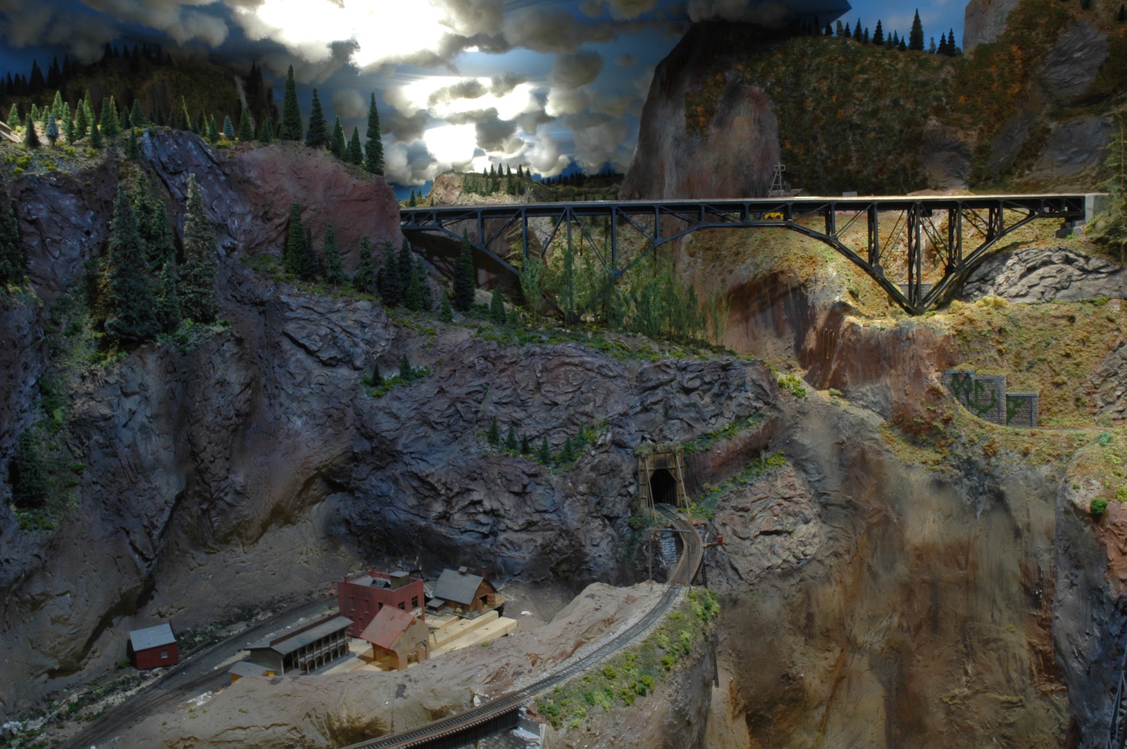
Photo 65 This is the view of a completely new hamlet on the layout. It is called Silver Hill and boasts a small flag stop station and mining operation. After the convention more structures will be added to this portion of the layout to add visual interest.
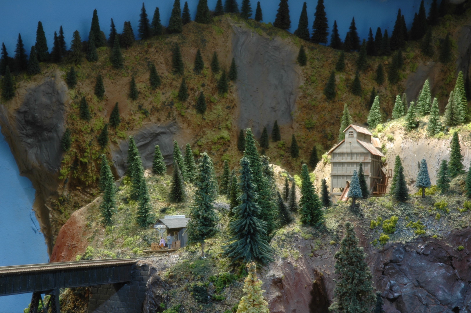
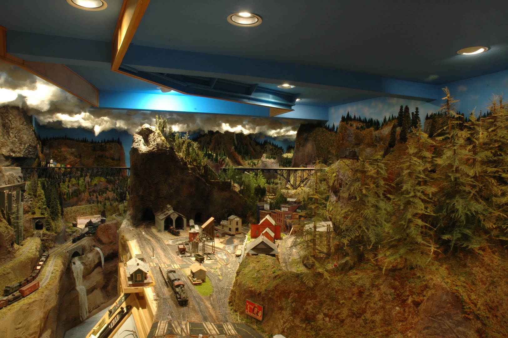
Photo 66 is a partial view of the Dry Gulch & Western layout. This is what the attendees of the National Narrow Gauge convention will be able to see during their visit to my layout. My layout is only one of the 36 excellent layouts open for tours during the convention. Everyone in the 4D should take advantage of this convention since it is right in your own backyard.
After the convention I plan on continuing scenery application to other areas of the layout. My two largest cities are still without structures! This will be my next targeted area to complete. I also have a large engine service facility to construct. So, the future holds many projects that will require my attention. I hope to see all of you 4D folks at the convention and especially when you visit my layout.
David